Hello,
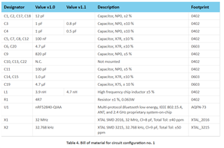
The datasheet shows example circuit configurations with C3=C4=1pF and L1=3.9nH. But the downloaded reference design shows C3=0.8pF, C4=0.5pF, L1=4.7nH, plus an empty position C22. Which one should be used?
Hello,
The datasheet shows example circuit configurations with C3=C4=1pF and L1=3.9nH. But the downloaded reference design shows C3=0.8pF, C4=0.5pF, L1=4.7nH, plus an empty position C22. Which one should be used?
Hi,
We released an alternative matching network in v1.1 of the PS, the one used in the reference design you downloaded:

Both are valid, but the v1.0 can be a little sensitive to differences in your layout (compared to our reference layout) and might cause high harmonics. v1.1 adds some margin to mitigate this. Note that no matter which one you choose you should always measure TX output power and harmonics in your board/layout, and if needed tune the RF matching network components. We can assist with this if you need.
Best regards,
Andreas
Hi,
We released an alternative matching network in v1.1 of the PS, the one used in the reference design you downloaded:

Both are valid, but the v1.0 can be a little sensitive to differences in your layout (compared to our reference layout) and might cause high harmonics. v1.1 adds some margin to mitigate this. Note that no matter which one you choose you should always measure TX output power and harmonics in your board/layout, and if needed tune the RF matching network components. We can assist with this if you need.
Best regards,
Andreas