This post is older than 2 years and might not be relevant anymore
More Info: Consider searching for newer posts

UART/Serial Port Emulation over BLE example doesn't receive over UART (only transmits)

I successfully compiled and loaded the UART/Serial Port Emulation over BLE example on an AdaFruit Feather board.

I can connect to the Nordic UART Service, then send data from the nRF Connect app (Rx Characteristic) to the Feather board (nRF52832) and see the data go out the Feather/nRF52832 UART and into my UART USB dongle and appear on the Linux minicom terminal.

What doesn't work is:

1) I never see the "UART started!" string when the application first starts.

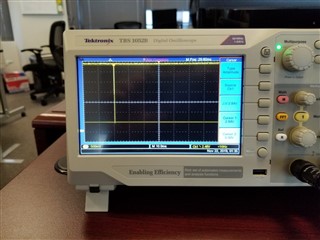
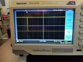
2) I type characters (with newline) on the Linux minicom terminal and I can see on the oscilloscope data on the Feather/RF52832 Rx line, but the application never sees an RX data interrupt fire, and therefore never sends the characters across BLE to the nRF Connect app.

Ubuntu Linux 16.04.6 LTS

S132 SoftDevice v7.0.1

Nordic SDK v16.0.0

(Downloading 'ble_app_uart_pca10040_s132.elf' to J-Link)

  • Hi,

    Are you using an unmodified version of the UART example in the SDK? Have you tried debugging and see if you get any errors?

  • Yes, I am using an unmodified version of the UART example in the SDK.

    I have the debugger running and see the NRF_UARTE_EVENT_ENDTX interrupt in uarte_irq_handler.

    However, I never see the RX interrupt activate (after typing from the terminal).

    I captured the signal from the Tx pin which shows delta V as 2.9V

    I then captured the signal from the Rx pin which shows delta V as 1.68V

    Is there possibly something set incorrectly on the RX GPIO input pin that would fight the incoming signal and prevent an interrupt?

  • I have solved the problem, but also found something very unusual.

    The Nordic "UART/Serial Port Emulation over BLE" example code sets the Rx pin to P0.08 and the Tx pin to P0.06.

    On the Adafruit Feather, the documentation and the silkscreen indicate where the Rx(P0.08) and Tx(P0.06) pins route to the header connector.

    Therefore I saw the following:

    1) If I connect the Tx/Rx wires per the Adafruit Feather silkscreen/documentation the Tx works, but the Rx does not. I can send data from the Nordic UART phone app to the board out the serial port and to the serial comm terminal, but I cannot send data from the serial comm terminal to the board, Rx doesn't work.

    2) If I switch the Tx/Rx wires (contrary to the hardware silkscreen/documentation) then it works both directions, which is great, however it motivates the question: How does the Tx path work (per #1 above) if the Tx wire is connected to the Rx pin incorrectly?

    3) In addition, in the setup stated in #2 above, if the Tx is on the Rx pin incorrectly, and I move the Rx wire to an adjacent pin, it works both ways as well!   How can the routing of the Tx/Rx pins change dynamically?

    Is there something (crosspoint switch?) in the nRF52832 that would explain this?

  • Hi,
    1) It might be that you have set the RX pin as output somewhere in your application. You can try to configure the pin as a general input pin and see if you can trigger an interrupt with it.
    As for 2) and 3), I would suggest to test another Adafruit Feather board and see if you can reproduce the same issue.
  • I found the problem. It was with the Adafruit setup. The JLink USB was enumerating as a serial port so I had two serial ports: the UART to the Tx and Rx pins on the Adafruit board, and the JLink USB. When the UART Rx wire was connected properly it would conflict with the JLink USB and the board would never trigger a RX interrupt.

    I solved the problem by using an nRF52 DK board and all is well with the UART now (the USB/JLink connection enumerates as a USB ACM device so it does not conflict with the UART).

Related