
nrf
nrf
Hi Hamid,
the reference design for the nRF51822 is used on the nRF51 DK and you can find the hardware layout files here: https://www.nordicsemi.com/-/media/Software-and-other-downloads/Dev-Kits/nRF51-DK/nRF51-DK---Hardware-files-1_2_0.zip. From these you should be able to see the relative placement as well as measure the length of the transmission lines
Best regards
Bjørn

Hi Bjon
first of all really thanks for you quick reply
i think my question was not clear i am only interested in antenna design for nrf51822 ,i follow this blog post ' General pcb design guidelines for nrf51' and its link is "https://devzone.nordicsemi.com/nordic/nordic-blog/b/blog/posts/general-pcb-design-guidelines-for-nrf51"
actually i want to use a chip antenna and then will connect it with nrf51, as shown below.
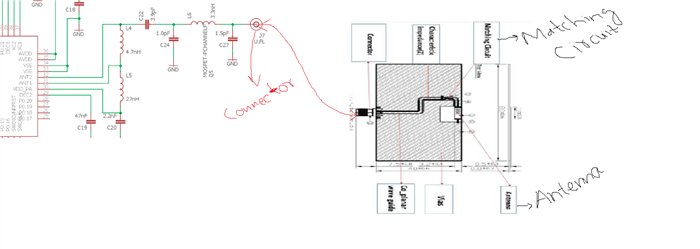
my question is, is it fine to use two matching circuit one for the chip antena as suggested by manufacturer and one which nordic suggested as shown in fig. and will it work in this way.it is only for testing purpose.
my second question is the chip antenna should be exactly 2.4 GHZ or if it is 2.45 GHZ does it matter.

Great 
Hi bjorn,
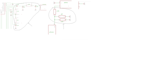
as you asked for reviewing my design when i am finished with it, so i am now done with it , so can you have a look for reviewing the matching circuit with antenna and the matching circuit with antenna on micro controller , so after connecting these two will it be fine. as shown below.
HI Hamid, can you provide the entire schematic in a pdf and the layout in Gerbers? I can make the case private if you like so that the shared files are only visible to you and me.
Best regards
Bjørn
HI Hamid,
I have taken a look at your layout and these are my comments:
nRF51x22-QFAx_Ref_Layout_v2.5.zip
Best regards
Bjørn
HI Hamid,
I have taken a look at your layout and these are my comments:
nRF51x22-QFAx_Ref_Layout_v2.5.zip
Best regards
Bjørn
Hi bjorn-spockeli,
thanks a lot for giving me these comments on my layout, i will do it and if necessary i will contact you, thanks once again for your help.
Kind regards
Hamid
Hi Hamid,
Happy to help. Just upload the gerbers once you have done the necessary corrections and I will review them again.
Best regards
Bjørn
Hi Bjørn,
Here is the gerbers files as you suggested to review it again, thanks.
Kind regards
Hamid
Thank you so much dear for your sincere help, it really help me in implementation.
Kind regards
Hamid