I tried to drive MAX30003 to get ECG signals through nrf52832.
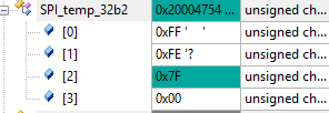
I use an analog signal instrument to give the standard ECG signals. Now,the nrf's SPI timing sequence is right, and the data I got from the MAX30003 RTOR registers(0X25) is right (HR values is similiar to the signal instrument ).But the data I read from ECG_FIFO is not true. Can I get some help?
#include <stdbool.h>
#include <stdint.h>
#include <stdio.h>
#include "app_uart.h"
#include "app_error.h"
#include "nrf_delay.h"
#include "nrf_gpio.h"
#include "boards.h"
#include "max30003.h"
#include "nrf_drv_spi.h"
#include "SEGGER_RTT.h"
#include "nrf_drv_pwm.h"


#define UART_TX_BUF_SIZE 256                         /**< UART TX buffer size. */
#define UART_RX_BUF_SIZE 1                           /**< UART RX buffer size. */

static nrf_drv_pwm_t m_pwm0 = NRF_DRV_PWM_INSTANCE(0);
#define APP_PWM_DEFAULT_CONFIG_1CH(period_in_us, pin)
#define USED_PWM(idx) (1UL << idx)
static uint8_t m_used = 0;

static void pwm(void)
{
    nrf_drv_pwm_config_t const config0 =
    {
        .output_pins =
        {
            MAX30003_PIN_FCLK | NRF_DRV_PWM_PIN_INVERTED,  // channel 0  Êä³öÒý½Å
            NRF_DRV_PWM_PIN_NOT_USED,             // channel 1
            NRF_DRV_PWM_PIN_NOT_USED,             // channel 2
            NRF_DRV_PWM_PIN_NOT_USED,             // channel 3
        },
        .irq_priority = APP_IRQ_PRIORITY_LOWEST,
        .base_clock   = NRF_PWM_CLK_16MHz,
        .count_mode   = NRF_PWM_MODE_UP,
        .top_value    = 256,
        .load_mode    = NRF_PWM_LOAD_COMMON,
        .step_mode    = NRF_PWM_STEP_AUTO
    };
    APP_ERROR_CHECK(nrf_drv_pwm_init(&m_pwm0, &config0, NULL));
    m_used |= USED_PWM(0);


			static uint16_t /*const*/ seq_values[] =
    {
         0x8000,
             0,
    };
    nrf_pwm_sequence_t const seq =
    {
        .values.p_common = seq_values,
        .length          = NRF_PWM_VALUES_LENGTH(seq_values),
        .repeats         = 0,
        .end_delay       = 0
    };

    (void)nrf_drv_pwm_simple_playback(&m_pwm0, &seq, 1, NRF_DRV_PWM_FLAG_LOOP);
}


void uart_error_handle(app_uart_evt_t * p_event)
{
    if (p_event->evt_type == APP_UART_COMMUNICATION_ERROR)
    {
        APP_ERROR_HANDLER(p_event->data.error_communication);
    }
    else if (p_event->evt_type == APP_UART_FIFO_ERROR)
    {
        APP_ERROR_HANDLER(p_event->data.error_code);
    }
}
/**********************************************************************************************
 * Ãè  Êö : ´®¿Ú³õʼ»¯¡£²¨ÌØÂÊ=115200bps
 * Èë  ²Î : ÎÞ
 * ·µ»ØÖµ : ÎÞ
 *********************************************************************************************/
void uart_init(void)
{
	  uint32_t err_code;
    const app_uart_comm_params_t comm_params =
    {
          RX_PIN_NUMBER,
          TX_PIN_NUMBER,
          RTS_PIN_NUMBER,
          CTS_PIN_NUMBER,
          APP_UART_FLOW_CONTROL_DISABLED,
          false,
          UART_BAUDRATE_BAUDRATE_Baud115200
    };

    APP_UART_FIFO_INIT(&comm_params,
                         UART_RX_BUF_SIZE,
                         UART_TX_BUF_SIZE,
                         uart_error_handle,
                         APP_IRQ_PRIORITY_LOW,
                         err_code);

    APP_ERROR_CHECK(err_code);
}


/**********************************************************************************************
 * Ãè  Êö : mainº¯Êý
 * Èë  ²Î : ÎÞ
 * ·µ»ØÖµ : ÎÞ
 *********************************************************************************************/
int main(void)
{
	  uint8_t SPI_temp_32b[4],SPI_temp_32b1[4],SPI_temp_32b2[4];
		uint8_t DataPacketHeader[20];
		signed long ecgdata;
		unsigned long data;

    uart_init();
		SEGGER_RTT_ConfigUpBuffer(0, NULL, NULL, 0, SEGGER_RTT_MODE_NO_BLOCK_SKIP);
	  nrf_delay_ms(100);

		nrf_gpio_cfg_output(MAX30003_PIN_FCLK);
		pwm();
		max30003_spi_init();
		max30003_init();

    while (true)
    {

			max30003_read_register(MAX30003_REGADDR_ECG_FIFO,SPI_temp_32b2);

			data = (SPI_temp_32b2[0] <<16)|(SPI_temp_32b2[1] <<8)|((SPI_temp_32b2[2] >>6)&0x03);
			ecgdata = (signed long) (data);

			printf("%d\r\n",ecgdata);

			max30003_read_register(MAX30003_REGADDR_RTOR,SPI_temp_32b);
			unsigned long RTOR_msb = (unsigned long) (SPI_temp_32b[0]);
			unsigned char RTOR_lsb = (unsigned char) (SPI_temp_32b[1]);

			unsigned long rtor = (RTOR_msb<<8 | RTOR_lsb);
			rtor = ((rtor >>2) & 0x3fff) ;
			float hr =  60 /((float)rtor*0.008);
			unsigned int HR = (unsigned int)hr;  // type cast to int
			unsigned int RR = (unsigned int)rtor*8 ;  //8ms

//			printf("%d\r\n",HR);

			DataPacketHeader[0] = 0x0A;
      DataPacketHeader[1] = 0xFA;
      DataPacketHeader[2] = 0x0C;
      DataPacketHeader[3] = 0;
      DataPacketHeader[4] = 0x02;

      DataPacketHeader[5] = ecgdata;
      DataPacketHeader[6] = ecgdata>>8;
      DataPacketHeader[7] = ecgdata>>16;
      DataPacketHeader[8] = ecgdata>>24;

      DataPacketHeader[9] =  RR ;
      DataPacketHeader[10] = RR >>8;
      DataPacketHeader[11] = 0x00;
      DataPacketHeader[12] = 0x00;

      DataPacketHeader[13] = HR ;
      DataPacketHeader[14] = HR >>8;
      DataPacketHeader[15] = 0x00;
      DataPacketHeader[16] = 0x00;

      DataPacketHeader[17] = 0x00;
      DataPacketHeader[18] = 0x0b;

//			for(int i=0;i<19;i++)
//			{app_uart_put(DataPacketHeader[i]);}

    }

}

/********************************************END FILE*******************************************/


 Fig 1
Fig 1  Fig 2
Fig 2 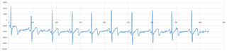 Fig 3
Fig 3