This post is older than 2 years and might not be relevant anymore
More Info: Consider searching for newer posts

Receiving data from UART via a peripheral device

Hi

I am working with a Nordic nrf52840dk using segge and sdk 16.

I am using the nordic UART example in examples/peripheral/uart.

The issue I am having is that my data being sent to this device can not be read from the nordic board.

Below is an example of the code going into my Putty terminal from my UART peripheral device.

1,1183,1,1169
1,1183,1,1169
1,1183,1,1169
1,1183,1,1169
1,1183,1,1169
1,1183,1,1169

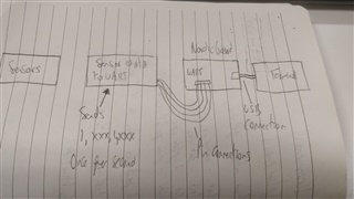
This device has 4 wire connections RX,TX,CTS and RTS. My connections are listed below:

Note this is the default.

#define RX_PIN_NUMBER  8
#define TX_PIN_NUMBER  6
#define CTS_PIN_NUMBER 7
#define RTS_PIN_NUMBER 5

The first thing i tried was running the code with no change to see if app_uart_get(&cr) would pull this data. Unfortunately it did not. It does however, pull data that i type into the terminal.

What I want to do is to take this data from the UART(Sensor data) and store it as a variable for handling later on.

I which to know how I can pull this data from the serial connection.

Side note when the device (UART) is plugged in printing from putty does not run. If I unplug the device then printing works fine.  Below is my main code (from example).
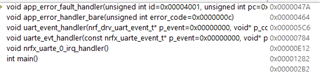
int main(void)
{
    uint32_t err_code;

    bsp_board_init(BSP_INIT_LEDS);

    const app_uart_comm_params_t comm_params =
      {
          RX_PIN_NUMBER,
          TX_PIN_NUMBER,
          RTS_PIN_NUMBER,
          CTS_PIN_NUMBER,
          UART_HWFC,
          false,
#if defined (UARTE_PRESENT)
          NRF_UARTE_BAUDRATE_115200
#else
          NRF_UARTE_BAUDRATE_115200
#endif
/*
#if defined (UART_PRESENT)
          NRF_UART_BAUDRATE_115200
#else
          NRF_UARTE_BAUDRATE_115200
#endif
*/
      };

    APP_UART_FIFO_INIT(&comm_params,
                         UART_RX_BUF_SIZE,
                         UART_TX_BUF_SIZE,
                         uart_error_handle,
                         APP_IRQ_PRIORITY_HIGH,
                         //APP_IRQ_PRIORITY_LOWEST,
                         err_code);

    APP_ERROR_CHECK(err_code);

#ifndef ENABLE_LOOPBACK_TEST
    printf("\r\nUART example started.\r\n");

    while (true)
    {
        uint8_t cr;
        while (app_uart_get(&cr) != NRF_SUCCESS);
        while (app_uart_put(cr) != NRF_SUCCESS);

        if (cr == 'q' || cr == 'Q')
        {
            printf(" \r\nExit!\r\n");

            while (true)
            {
                // Do nothing.
            }
        }
    }
#else

    // This part of the example is just for testing the loopback .
    while (true)
    {
        uart_loopback_test();
    }
#endif
}

Parents
  • Hi,

    It is not entirely clear to me, but the serial terminal on the PC is via the onboard debugger, right (USB connector on the left of the board)? If you are using that (or have the debugger enabled in general so that IF OFF is not asserted, then you should use different pins for the external UART device. In other words, connect the UART pins between the nRF and another device to some available GPIO pins, and update the pin number defines.

  • Thanks for your response, I am using the onboard usb connector (the one in the top-middle of the board). This is where my putty serial terminal connects to. Jlink CDC UART PORT(COM5)

    I have tried redefining the pinouts to:

    #define RX_PIN_NUMBER  NRF_GPIO_PIN_MAP(0,3)//8
    #define TX_PIN_NUMBER  NRF_GPIO_PIN_MAP(0,28)//6
    #define CTS_PIN_NUMBER NRF_GPIO_PIN_MAP(0,4)//7
    #define RTS_PIN_NUMBER NRF_GPIO_PIN_MAP(0,29)//5

    I have then connected my device to those pinout.

    However, I now no longer see that information (from the uart device) to putty, nor can I use a printf command and see the result.

    When I  run this through the dubugger after running the APP_UART_FIFO_INIT and checking the error code it goes to NRF_BREAKPOINT_COND;

    I then get this in the call stack area of the debugger.

    What other details do you need to help resolve this issue?

  • Hi Thomas,

    I want to start by checking if my understanding is correct. You use UART for two things:

    • Command-line / logging interface with a PC
    • Communicating with an external device

    Do you have these enabled at the same time? If so, you need to use two UART peripherals and configure a separate set of pins etc. for both. If this is not the case, then please explain in a bit more detail what you are doing (perhaps with a drawing?)

  • Hi Einar,

    I am using both command line with a PC and communicating with an external device. 

    However, I only want to receive data from the external UART device and do not need command line logging as well.

    I have a single UART peripheral device that I want to connect to the NRF52840 device and, I want to read its data as shown above.

    But the device outputs data straight to the putty terminal and, I can't find a way to read it.

    Then I decided to print to the terminal using the Nordic board. I can see a response from data i type in but, not from the UART board.

    Below is an image of my setup:

    Thanks

  • Hi Thomas,

    The thing here is that you are connecting the sensor to the same pins that the nRF uses for UART with the PC. And this is why you see the data on the UART terminal on your PC. This is probably not what you want to do.

    You write that you "do not need command-line logging as well", and in that case, you should just disable the logging module in sdk_config.h. But your drawing shows that you use it with a terminal, so I am not sure?

    In any case, the point is that you should not use pin 5-8 for the UART connection with your sensor since that is connected to the debugger (which acts as a UART-USB bridge here). Use some other available pins, and configure the UART driver appropriately.

    If you do want to communicate with both the sensor and a UART terminal via USB (as the drawing shows), then you need to use two UART peripherals. That is no problem since the nRF52840 has two UART peripherals. Alternatively, you can use RTT for logging (if needed), and just use UART for communicating with the sensor. This is probably the simplest, since you can just take a UART example and change the pins, and you are ready.

Reply
  • Hi Thomas,

    The thing here is that you are connecting the sensor to the same pins that the nRF uses for UART with the PC. And this is why you see the data on the UART terminal on your PC. This is probably not what you want to do.

    You write that you "do not need command-line logging as well", and in that case, you should just disable the logging module in sdk_config.h. But your drawing shows that you use it with a terminal, so I am not sure?

    In any case, the point is that you should not use pin 5-8 for the UART connection with your sensor since that is connected to the debugger (which acts as a UART-USB bridge here). Use some other available pins, and configure the UART driver appropriately.

    If you do want to communicate with both the sensor and a UART terminal via USB (as the drawing shows), then you need to use two UART peripherals. That is no problem since the nRF52840 has two UART peripherals. Alternatively, you can use RTT for logging (if needed), and just use UART for communicating with the sensor. This is probably the simplest, since you can just take a UART example and change the pins, and you are ready.

Children
  • Hi Einar,

    Sorry for the confusion I do not need to use the terminal.

    • So i need to disable logging in the sdk_config.h?
    • Move the UART pin definitions from 5-8
    • Then I should be able to use the app_uart_get(&cr) to get the data?

    Also what #define is for the logging module?

    I also presume I need to make this 0.

  • Hi,

    Yes, that is correct. Set NRF_LOG_ENABLED to 0 (if it is not already). That will disable UART logging. And use other (non-used) GPIO pins. That should be all Slight smile

  • Ok I've changed my pin outs to below:

    #define RX_PIN_NUMBER  NRF_GPIO_PIN_MAP(0,13)//8
    #define TX_PIN_NUMBER  NRF_GPIO_PIN_MAP(0,11)//6
    #define CTS_PIN_NUMBER NRF_GPIO_PIN_MAP(0,12)//7
    #define RTS_PIN_NUMBER NRF_GPIO_PIN_MAP(0,10)//5

    I have then migrated my pin connections from my UART device to this.

    However, when I run though the debugger and have a break point on:

    while (app_uart_get(&cr) != NRF_SUCCESS);

    It never runs. Therefore, I am not reading this data. What am I doing wrong?

  • I cannot say without knowing more. Can you share your code? At least the UART related? What state is the device in when it does not reach your breakpoint? have you tried stepping (will not work well with the SoftDevice enabled).

  • I have tried stepping through the code and it holds on:

    while (app_uart_get(&cr) != NRF_SUCCESS);

    My main code is:

    /**
     * Copyright (c) 2014 - 2019, Nordic Semiconductor ASA
     *
     * All rights reserved.
     *
     * Redistribution and use in source and binary forms, with or without modification,
     * are permitted provided that the following conditions are met:
     *
     * 1. Redistributions of source code must retain the above copyright notice, this
     *    list of conditions and the following disclaimer.
     *
     * 2. Redistributions in binary form, except as embedded into a Nordic
     *    Semiconductor ASA integrated circuit in a product or a software update for
     *    such product, must reproduce the above copyright notice, this list of
     *    conditions and the following disclaimer in the documentation and/or other
     *    materials provided with the distribution.
     *
     * 3. Neither the name of Nordic Semiconductor ASA nor the names of its
     *    contributors may be used to endorse or promote products derived from this
     *    software without specific prior written permission.
     *
     * 4. This software, with or without modification, must only be used with a
     *    Nordic Semiconductor ASA integrated circuit.
     *
     * 5. Any software provided in binary form under this license must not be reverse
     *    engineered, decompiled, modified and/or disassembled.
     *
     * THIS SOFTWARE IS PROVIDED BY NORDIC SEMICONDUCTOR ASA "AS IS" AND ANY EXPRESS
     * OR IMPLIED WARRANTIES, INCLUDING, BUT NOT LIMITED TO, THE IMPLIED WARRANTIES
     * OF MERCHANTABILITY, NONINFRINGEMENT, AND FITNESS FOR A PARTICULAR PURPOSE ARE
     * DISCLAIMED. IN NO EVENT SHALL NORDIC SEMICONDUCTOR ASA OR CONTRIBUTORS BE
     * LIABLE FOR ANY DIRECT, INDIRECT, INCIDENTAL, SPECIAL, EXEMPLARY, OR
     * CONSEQUENTIAL DAMAGES (INCLUDING, BUT NOT LIMITED TO, PROCUREMENT OF SUBSTITUTE
     * GOODS OR SERVICES; LOSS OF USE, DATA, OR PROFITS; OR BUSINESS INTERRUPTION)
     * HOWEVER CAUSED AND ON ANY THEORY OF LIABILITY, WHETHER IN CONTRACT, STRICT
     * LIABILITY, OR TORT (INCLUDING NEGLIGENCE OR OTHERWISE) ARISING IN ANY WAY OUT
     * OF THE USE OF THIS SOFTWARE, EVEN IF ADVISED OF THE POSSIBILITY OF SUCH DAMAGE.
     *
     */
    /** @file
     * @defgroup uart_example_main main.c
     * @{
     * @ingroup uart_example
     * @brief UART Example Application main file.
     *
     * This file contains the source code for a sample application using UART.
     *
     */
    
    #include <stdbool.h>
    #include <stdint.h>
    #include <stdio.h>
    #include "app_uart.h"
    #include "app_error.h"
    #include "nrf_delay.h"
    #include "nrf.h"
    #include "bsp.h"
    #if defined (UART_PRESENT)
    #include "nrf_uart.h"
    #endif
    #if defined (UARTE_PRESENT)
    #include "nrf_uarte.h"
    #endif
    
    
    //#define ENABLE_LOOPBACK_TEST  /**< if defined, then this example will be a loopback test, which means that TX should be connected to RX to get data loopback. */
    
    #define MAX_TEST_DATA_BYTES     (15U)                /**< max number of test bytes to be used for tx and rx. */
    #define UART_TX_BUF_SIZE 256                         /**< UART TX buffer size. 256*/
    #define UART_RX_BUF_SIZE 256                         /**< UART RX buffer size. 256*/
    
    void uart_error_handle(app_uart_evt_t * p_event)
    {
        if (p_event->evt_type == APP_UART_COMMUNICATION_ERROR)
        {
            APP_ERROR_HANDLER(p_event->data.error_communication);
        }
        else if (p_event->evt_type == APP_UART_FIFO_ERROR)
        {
            APP_ERROR_HANDLER(p_event->data.error_code);
        }
    }
    
    
    #ifdef ENABLE_LOOPBACK_TEST
    /* Use flow control in loopback test. */
    #define UART_HWFC APP_UART_FLOW_CONTROL_ENABLED
    
    /** @brief Function for setting the @ref ERROR_PIN high, and then enter an infinite loop.
     */
    static void show_error(void)
    {
    
        bsp_board_leds_on();
        while (true)
        {
            // Do nothing.
        }
    }
    
    
    /** @brief Function for testing UART loop back.
     *  @details Transmitts one character at a time to check if the data received from the loopback is same as the transmitted data.
     *  @note  @ref TX_PIN_NUMBER must be connected to @ref RX_PIN_NUMBER)
     */
    static void uart_loopback_test()
    {
        uint8_t * tx_data = (uint8_t *)("\r\nLOOPBACK_TEST\r\n");
        uint8_t   rx_data;
    
        // Start sending one byte and see if you get the same
        for (uint32_t i = 0; i < MAX_TEST_DATA_BYTES; i++)
        {
            uint32_t err_code;
            while (app_uart_put(tx_data[i]) != NRF_SUCCESS);
    
            nrf_delay_ms(10);
            err_code = app_uart_get(&rx_data);
    
            if ((rx_data != tx_data[i]) || (err_code != NRF_SUCCESS))
            {
                show_error();
            }
        }
        return;
    }
    #else
    /* When UART is used for communication with the host do not use flow control.*/
    #define UART_HWFC APP_UART_FLOW_CONTROL_DISABLED
    #endif
    
    
    /**
     * @brief Function for main application entry.
     */
    int main(void)
    {
        uint32_t err_code;
    
        bsp_board_init(BSP_INIT_LEDS);
    
        const app_uart_comm_params_t comm_params =
          {
              RX_PIN_NUMBER,
              TX_PIN_NUMBER,
              RTS_PIN_NUMBER,
              CTS_PIN_NUMBER,
              UART_HWFC,
              false,
    #if defined (UARTE_PRESENT)
              NRF_UARTE_BAUDRATE_115200
    #else
              NRF_UARTE_BAUDRATE_115200
    #endif
    /*
    #if defined (UART_PRESENT)
              NRF_UART_BAUDRATE_115200
    #else
              NRF_UARTE_BAUDRATE_115200
    #endif
    */
          };
    
        APP_UART_FIFO_INIT(&comm_params,
                             UART_RX_BUF_SIZE,
                             UART_TX_BUF_SIZE,
                             uart_error_handle,
                             APP_IRQ_PRIORITY_LOWEST,
                             err_code);
    
        APP_ERROR_CHECK(err_code);
    
    #ifndef ENABLE_LOOPBACK_TEST
        //printf("\r\nUART example started.\r\n");
    
        while (true)
        {
            uint8_t cr;
            while (app_uart_get(&cr) != NRF_SUCCESS);
            while (app_uart_put(cr)  != NRF_SUCCESS);
            if (cr == 't' || cr == 't')
            {
                printf("\r\n Test passed\r\n");
            }
            if (cr == 'q' || cr == 'Q')
            {
                printf(" \r\nExit!\r\n");
    
                while (true)
                {
                    // Do nothing.
                }
            }
        }
    #else
    
        // This part of the example is just for testing the loopback .
        while (true)
        {
            uart_loopback_test();
        }
    #endif
    }
    
    
    /** @} */
    

    I cant share the config code its too large.

    Using sdk 16 NRF52840 pca10056.

    Also my peripheral device posts data once per second to the Nordic board.

    Below is showing my connection setup (physically).

Related