This post is older than 2 years and might not be relevant anymore
More Info: Consider searching for newer posts

GPIO setup parameters for AoA Antenna switching

I have an issue with getting the I/Os correctly setup for antenna switching.

I am running the radio_test example code with the following modifications. 

So far, I have the following code for the GPIO setup:

//Defines are at top of file
#define ANT1 NRF_GPIO_PIN_MAP(0,17)
#define ANT2 NRF_GPIO_PIN_MAP(1,8)
#define ANT3 NRF_GPIO_PIN_MAP(1,7)
#define ANT4 NRF_GPIO_PIN_MAP(1,6)

//other support code

//Pin config
nrf_gpio_pin_clear(ANT1);
nrf_gpio_cfg_output(ANT1);
nrf_gpio_pin_clear(ANT2);
nrf_gpio_cfg_output(ANT2);
nrf_gpio_pin_clear(ANT3);
nrf_gpio_cfg_output(ANT3);
nrf_gpio_pin_clear(ANT4);
nrf_gpio_cfg_output(ANT4);

//DFE pin config
NRF_RADIO->PSEL.DFEGPIO[0] = ANT1; //(P0.17)
NRF_RADIO->PSEL.DFEGPIO[1] = ANT2; //(P1.08)
NRF_RADIO->PSEL.DFEGPIO[2] = ANT3; //(P1.07)
NRF_RADIO->PSEL.DFEGPIO[4] = ANT4; //(P1.06)

NRF_RADIO->SWITCHPATTERN = 1; //Only P0.07 active
NRF_RADIO->SWITCHPATTERN = 2; //Only P1.08 active
NRF_RADIO->SWITCHPATTERN = 4; //Only P1.07 active
NRF_RADIO->SWITCHPATTERN = 8; //Only P1.06 active

NRF_RADIO->DFEMODE = RADIO_DFEMODE_DFEOPMODE_AoA;
NRF_RADIO->DFECTRL1 = 10 << RADIO_DFECTRL1_NUMBEROF8US_Pos | 
                       1 << RADIO_DFECTRL1_DFEINEXTENSION_Pos;

Then in the radio_test.c file, I include in the function radio_rx( ...)

uint32_t g_iq_packet[RADIO_MAX_PAYLOAD_LEN];

void radio_rx(....)
{
//orig example code still exists here, only not shown
    NRF_RADIO->DFEPACKET.PTR = (uint32_t)g_iq_packet;

}

From a board running the radio_test example, I issue the 'start_tx_modulated_carrier' command the immediately issue the 'start_rx" command on a seperate DK also running the radio_test example with the above modifications.

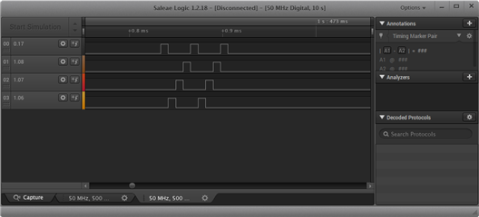
I expected to see a short duration square wave on each of the antenna GPIO pins, so, 4 square waves cascading in time. However from my logic analyzer capture, you can clearly see that is not the case.

How should I be setting up the config registers to fire each of the pins.  Nothing else is connected to the board except the logic analyzer.

Also, how do I correlate the IQ data from the DFEPACKET.PTR to the specific antenna?
Parents
  • Hi,

    as documentation says:

    The first write to SWITCHPATTERN is the GPIO pattern applied from the call of TASKS_TXEN or TASKS_RXEN until the first antenna switch is triggered. The second write sets the pattern for the reference period and is applied at the start of the guard period. The following writes set the pattern for the remaining switch slots and are applied at the start of each switch slot. If writing beyond the total number of antenna slots, the pattern will wrap to SWITCHPATTERN[2] and start over again.

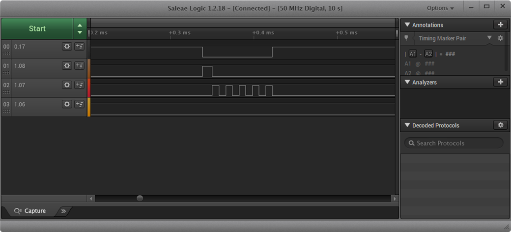
    As I understand, you have receiver powered-on continuously (at least for the time we see at LA screenshot). So head and tail corresponds to  PSEL.DFEGPIO[0]. Then DFE pattern comes on, PSEL.DFEGPIO[1] is active. Then should be interleaving PSEL.DFEGPIO[2] and PSEL.DFEGPIO[3], but it seems you made a typo at line 23.

  • HI Dmitry,

    First off, thank you for catching that typo. it helped explain the inactivity of the 4th line in the analyzer trace.

    Next: What documentation? All I have is a product spec and the infocenter snippet on SWITCHPATTERN, both of which dont have that level of info you had posted. Where are you finding that?

    Is there a way to have the radio test example to continuously send CTE?

    I have modified my switchpattern to the following:

    NRF_RADIO->SWITCHPATTERN = 16; 
    NRF_RADIO->SWITCHPATTERN = 32; 
    NRF_RADIO->SWITCHPATTERN = 1; //Only P0.07 active
    NRF_RADIO->SWITCHPATTERN = 2; //Only P1.08 active
    NRF_RADIO->SWITCHPATTERN = 4; //Only P1.07 active
    NRF_RADIO->SWITCHPATTERN = 8; //Only P1.06 active
    

    The first two patterns (16 and 32) are dummy patterns so the remaining 4 would be looped when I ask for multiple IQ samples. Is this the correct way of doing that?

    This is now my pattern coming out of the LA

    The quantity of IQ samples is dictated by this:

    NRF_RADIO->DFECTRL1 = 10 << RADIO_DFECTRL1_NUMBEROF8US_Pos;

    So am I to understand that out of the 10 I/Q samples, Sample 1, 5 and 9 come from antenna pattern 1,  then samples 2,6 and 10 come from antenna pattern 2, etc...?

  • Hi,

    Next: What documentation? All I have is a product spec and the infocenter snippet on SWITCHPATTERN, both of which dont have that level of info you had posted. Where are you finding that?

    It's from product specification. I'm working with nRF52811, for nRF52833 you can find it here.

    Is there a way to have the radio test example to continuously send CTE?

    What do you mean "continuously"?  Receiver should catch a sync word, then DFE can be started, you can't capture a "clear" tone. Sure, you can modify a radio test example to append CTE to each packet.

    The first two patterns (16 and 32) are dummy patterns so the remaining 4 would be looped when I ask for multiple IQ samples. Is this the correct way of doing that?

    You have to activate one of your antennas during all periods, including first and second ones.  

    So am I to understand that out of the 10 I/Q samples, Sample 1, 5 and 9 come from antenna pattern 1,  then samples 2,6 and 10 come from antenna pattern 2, etc...?

    It's most vague part of documentation.. I still couldn't figure out what means "Signed value offset before starting sampling in number of 16M cycles relative to the beginning of the REFERENCE state - 12 us after switching start". What I have found by experiments - first samples are from reference period (8 samples if you set TSAMPLESPACINGREF=1us), then 1us skipped, then continuous sampling with rate set by TSAMPLESPACING, and here you'll have all "wrong" samples at switching periods too...  A reference period allows you to calculate frequency offset (don't expect an exact 250 kHz, it will vary in a wide range). I suggest you to set oversampling to 0.125us and visualize received IQ data, then you can find points at sine wave where phase has changed and find samples that match to each antenna.

Reply
  • Hi,

    Next: What documentation? All I have is a product spec and the infocenter snippet on SWITCHPATTERN, both of which dont have that level of info you had posted. Where are you finding that?

    It's from product specification. I'm working with nRF52811, for nRF52833 you can find it here.

    Is there a way to have the radio test example to continuously send CTE?

    What do you mean "continuously"?  Receiver should catch a sync word, then DFE can be started, you can't capture a "clear" tone. Sure, you can modify a radio test example to append CTE to each packet.

    The first two patterns (16 and 32) are dummy patterns so the remaining 4 would be looped when I ask for multiple IQ samples. Is this the correct way of doing that?

    You have to activate one of your antennas during all periods, including first and second ones.  

    So am I to understand that out of the 10 I/Q samples, Sample 1, 5 and 9 come from antenna pattern 1,  then samples 2,6 and 10 come from antenna pattern 2, etc...?

    It's most vague part of documentation.. I still couldn't figure out what means "Signed value offset before starting sampling in number of 16M cycles relative to the beginning of the REFERENCE state - 12 us after switching start". What I have found by experiments - first samples are from reference period (8 samples if you set TSAMPLESPACINGREF=1us), then 1us skipped, then continuous sampling with rate set by TSAMPLESPACING, and here you'll have all "wrong" samples at switching periods too...  A reference period allows you to calculate frequency offset (don't expect an exact 250 kHz, it will vary in a wide range). I suggest you to set oversampling to 0.125us and visualize received IQ data, then you can find points at sine wave where phase has changed and find samples that match to each antenna.

Children
  • Thanks for pointing out the specific section in the docs. If you guys are still taking suggestions on document updates, it would be helpful to reference that section from the registers section item on SWITCHPATTERN as well.

    From what I can tell, when I run the TX and RX versions of the radio test, I need to "START_TX_MODULATED_CARRIER" on the TX board before I "START_RX" on the receiver board. However, if I try START_RX again on the RX board, I dont get new IQ data. This suggests that the "START_TX_MODULATED_CARRIER" is a single shot and needs to be typed in every time I want to receive an IQ sample.  However, I am gathering that its a single-shot.

    So, instead of dummy patterns, I should do something like: 1,2,1,2,3,4 ( where the 1,2,3,4 sequence would repeat?)

    Are you saying that 'wrong' data is written to the IQ buffer for the first two elements because of the guard period and the reference period?  If you could provide an example, It would be much clearer to me.  It almost sounds like I need to receive some data and do calculation to have the rest of the data make sense...

Related