This post is older than 2 years and might not be relevant anymore
More Info: Consider searching for newer posts

Uneven current spikes during TX

Hello Support Engineers,

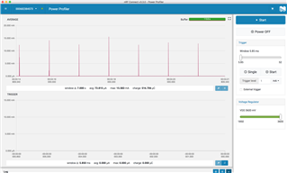
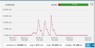
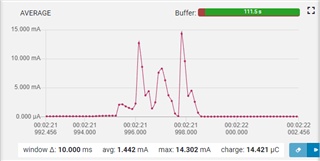
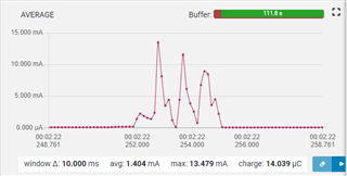
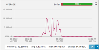
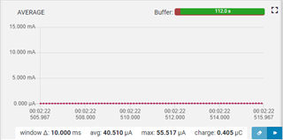
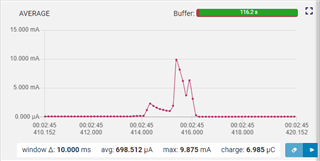
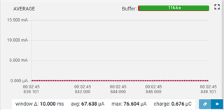
I have observed some interesting behaviour on my custom board vs the DK. In the DK, the current spikes is very even and steady around 10mA. However, on my board, the current spikes seems to be all over the place. Both are equipped with the Low frequency clock, external 10uH and 15nH inductor for DCDC.

I should also mentioned that in my custom board, I have another Ti DCDC convertor that that drops the input 3.6VDC from the PPK to 2.8V DC for feeding the Nrf52832. and I compare that to the DK tuning at 2.8V, set from the PPK. 

Please see the attached screen capture of the PPK. The current is measured at the input of the Ti DCDC convertor. Is it something I need to worry about?

Best Regards,

Nelson


Parents
  • Hi, what do you mean with "the current spikes seems to be all over the place". Do you mean the peak current value or the frequency of the spikes?

    What is the software doing? It looks like there's a 1 second interval between the spikes, is this advertising? Can you zoom in to one of the spikes? There's also a trigger window below. Can you try to trigger on the spike to get a higher resolution plot? Maybe we can see what is actually going on there.

  • Dear Stian,

    Here are the current diagrams for the device. The first set below are non-connected (advertising). I have exploded the view for 4 consecutive spikes

    As you can see, the peak current ranges from 15.3 to 10.16. The base current is also captured below.

    I am questioning whether I should be worrying about the 5 mA difference between spikes. I am sorry that I forget to capture the overall current pictures.

    The diagrams are for connected (non-advertising) currents. The connected currents for 2 consecutive spikes  are also captured below.

    Base currents are as follows:

    The overall connected current pictures included below:

    As you can see, there is also 3 mA peak difference as well in the connected case. Is this normal expected behavior where the peak current varies by almost 30% between spikes?

    As a reminder, the current are input to the external Texas Instrument DC/DC converter so I expects the spikes be be somehow smoothed by the converter. 

    Best regards,

    Nelson

Reply
  • Dear Stian,

    Here are the current diagrams for the device. The first set below are non-connected (advertising). I have exploded the view for 4 consecutive spikes

    As you can see, the peak current ranges from 15.3 to 10.16. The base current is also captured below.

    I am questioning whether I should be worrying about the 5 mA difference between spikes. I am sorry that I forget to capture the overall current pictures.

    The diagrams are for connected (non-advertising) currents. The connected currents for 2 consecutive spikes  are also captured below.

    Base currents are as follows:

    The overall connected current pictures included below:

    As you can see, there is also 3 mA peak difference as well in the connected case. Is this normal expected behavior where the peak current varies by almost 30% between spikes?

    As a reminder, the current are input to the external Texas Instrument DC/DC converter so I expects the spikes be be somehow smoothed by the converter. 

    Best regards,

    Nelson

Children
  • So first your question if it's normal to see 30% variation in TX peak current. No, that's not normal. The only time I've seen varying TX current is when you have poor antenna matching. Then the TX current will be different based on which radio channel you are transmitting on. And since the channel is changing at each TX spike, you will see different currents on the TX spikes. I've seen maybe 1mA difference at 0dBm. Are you using higher dBm? At 4dBm you might get such a big difference in peak current.

    Are you able to power the chip directly from the PPK, not through the onboard regulator? Then we can rule out if it's because of the regulator. Since it's a switching regulator it draws current in pulses, so maybe that's what we are seeing. What is the name of the regulator?

    Other than that it could be just aliasing in the plot since the resolution is not that good. You can maybe try to increase the advertising TX payload to 31 bytes so that it transmits more data, and so that the TX event lasts longer. Then see if the plot looks different.

    Anyways, I would check the antenna matching network first. Is the signal strength similar to the DK? If it's worse than the DK, it might indicate some issues with the matching network.

Related