Hello,
I am struggling to solve 2 problems ,
1st :
I have 4 AAA cells (2 in series each ) to make a good power source !
The Problem :
I have to measure the battery voltage(Input Line) to blink a LED when it falls below 2.0V , The Experiment setup I am using contains a POT (10K) which acts as a draining battery(voltage drops) , but the value I get from the wiper into my analog pin of NRF is between 53 to 450 occasionally going to 800 , however on arduino its spot on between 0 to 1024 , can I get the same here , the 10 bit SAADC res is defined in SDK Config I didn't touch that. Is the value 53 to 450 correct ??
2nd :
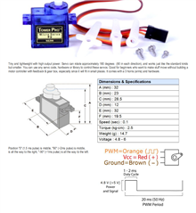
I have a servo ! connected to the same power source , I have a 4th wire on the servo that gives me the position of the servo !
The plan
I am going to write a function that increments the servo position a little and then monitor the analog signal on the 4th wire if it changes the shaft moved , if it didn't I will assume that something is blocking the shaft , so I will reverse the servo , and stop it from damaging something.
The problem :
I do not know how to convert the value that i receive from the SAADC example (I connected a 10K POT on A0 pin ) , The Infocenter says NRF52 is capable of 8Bit / 10 bit resolution , Where to select the resolution , Coming from Arduino analogRead is the goto function to do such calculations , my 10K POT shows 53 to 450 integer values(is that right ??) how do I map these values to voltage , and what resolution is those values ?
On the servo problem , I am using a PWM Library , for some odd reasons my Servo uses '2' as 0 position and '15' as 180Deg position(again is that right ??) , on the arduino side 0 ~ 255 and I have 255 Positions to put my servo in , here NRF52 However its 2~15 only. , However I am fine with 2~15 as long as Servo Moves 90 Deg , now I have that 4th wire to track the position again , how do I read it , compare it to previous position , then move again.
How do I get it to work the arduino way , that is 0 is servo 0 and 255 is servo 180 ??
I understand that the Nordic Product is very powerful and could get these things done easily if used the right way. However I am no expert in electronics nor an expert in C Programming , I mostly do python (good language at Application Level) , so In case if someone answers to my question please be brief and simplify with example and comments (I understand its more work to answer to noob).
Also if I am thinking if I fail to solve the problem with reasonable solution , I would put on an arduino that communicates with an NRF Chip via GPIO Signals (Poor Mans I2C Hahaha (Coz I have not dared to look at the I2C Example)) , The arduino would be my primary chip, that only toggles NRF When in need of BLE , which I do not want to do , since I know the chip is capable of doing what I want.
My Hardware and Setup
SDK 150
BLE Example is being used
NRF52 DK
Servo Code
#include <stdbool.h>
#include <stdint.h>
#include "nrf.h"
#include "app_error.h"
#include "bsp.h"
#include "nrf_delay.h"
#include "app_pwm.h"

APP_PWM_INSTANCE(PWM1,1);                   // Create the instance "PWM1" using TIMER1.

int main(void)
{
    ret_code_t err_code;
    uint8_t SERVO_PIN = 4;

    /* 1-channel PWM, 50Hz, output on DK LED pins, 20ms period */
    app_pwm_config_t pwm1_cfg = APP_PWM_DEFAULT_CONFIG_1CH(20000L, SERVO_PIN);

    /* Switch the polarity of the first channel. */
    pwm1_cfg.pin_polarity[0] = APP_PWM_POLARITY_ACTIVE_HIGH;

    /* Initialize and enable PWM. */
    err_code = app_pwm_init(&PWM1,&pwm1_cfg,NULL);
    APP_ERROR_CHECK(err_code);
    app_pwm_enable(&PWM1);

    uint8_t servo_pos_max = 10;
    uint8_t servo_pos_min = 5;
    while (true)
    {
        /* Set the duty cycle - keep trying until PWM is ready... */
        while (app_pwm_channel_duty_set(&PWM1, 0, servo_pos_max) == NRF_ERROR_BUSY);
        nrf_delay_ms(5000);
        while (app_pwm_channel_duty_set(&PWM1, 0, servo_pos_min) == NRF_ERROR_BUSY);
        nrf_delay_ms(5000);
     }

}
The Servo Code , Jitters the servo back and forth briskly sometimes and sometimes it works properly ! I have attached a video of this code working below please have a look , The servo ain't busted , it works very well on Arduino , also I dont know where did Sigurd got 5 and 10 value from why not 0 and 255 ???
SAADC Example Code for analog measurements (Would not it be nice if it could have been as simple as just one function as in Arduino ! (Sure this one gives more flexibilty)) or the maximum is only 3V ? measurement on Analog Pin..
void saadc_callback(nrf_drv_saadc_evt_t const * p_event)
{
    if (p_event->type == NRF_DRV_SAADC_EVT_DONE)
    {
        ret_code_t err_code;

        err_code = nrf_drv_saadc_buffer_convert(p_event->data.done.p_buffer, SAMPLES_IN_BUFFER);
        APP_ERROR_CHECK(err_code);

        int i;
        printf("ADC event number: %d \n", (int)m_adc_evt_counter);
        int average = 0;

        for (i = 0; i < SAMPLES_IN_BUFFER; i++)
        {
            //printf("%d \n", p_event->data.done.p_buffer[i]);
            average = average + p_event->data.done.p_buffer[i];
        }
        printf("Average %d \n",(average / SAMPLES_IN_BUFFER));
        average = average / SAMPLES_IN_BUFFER;

        double voltage = (((average-50.0f) / (500.0f-50.0f)) * (5.0f-1.0f)) + 1.0f;
        printf("Voltage %ld \n",voltage);

        m_adc_evt_counter++;
    }
}
Here is the Arduino Code for Simple Voltage Measurement ! , I was kind of looking something along these lines...
float floatMap(float x, float in_min, float in_max, float out_min, float out_max) {
  return (x - in_min) * (out_max - out_min) / (in_max - in_min) + out_min;
}

// the setup routine runs once when you press reset:
void setup() {
  // initialize serial communication at 9600 bits per second:
  Serial.begin(9600);
}

// the loop routine runs over and over again forever:
void loop() {
  // read the input on analog pin A0:
  int analogValue = analogRead(A0);
  // Rescale to potentiometer's voltage (from 0V to 5V):
  float voltage = floatMap(analogValue, 0, 1023, 0, 5);

  // print out the value you read:
  Serial.print("Analog: ");
  Serial.print(analogValue);
  Serial.print(", Voltage: ");
  Serial.println(voltage);
  delay(10);
}