Hello,
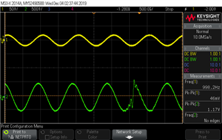
I am trying to sample and reconstruct an audio signal using the SAADC and I2S respectively. I have a double buffer setup for the SAADC, where we process the data in one buffer while sampling in the other, but I am getting discontinuities in the output signal every time saadc_handler() is called. The attached scope shot captures the analog input waveform (yellow) and reconstructed output from I2S codec (green). It has been verified that the discontinuity happens exactly when SAADC changes output buffer from one to the other. My understanding is that the I2S output stream is set up correctly (we have tested with this i2s_example, and it worked perfectly), so I am assuming there is something I need to change when sampling.
The sampling and reconstruction frequency are both at 31.25 kHz, and each input buffer size is 1024 (with an output buffer size of 2048).
#include <nrf.h>
#include <stdbool.h>
#include <stdint.h>
#include <stdio.h>
#include <string.h>
#include <stdlib.h>

#include "nrf.h"
#include "nrf_gpio.h"
#include "nrf_delay.h"
#include "nrf_twi_mngr.h"
#include "nrf_drv_spi.h"
#include "app_util_platform.h"
#include "nordic_common.h"
#include "app_timer.h"
#include "mem_manager.h"
#include "nrf_drv_clock.h"
#include "nrf_drv_gpiote.h"
#include "nrf_drv_saadc.h"
#include "nrf_drv_ppi.h"
#include "nrf_drv_timer.h"
#include "nrf_power.h"
#include "nrf_log.h"
#include "nrf_log_ctrl.h"
#include "nrf_log_default_backends.h"
#include "nrf_dfu_utils.h"
#include "nrf_dfu_settings.h"

#define SAADC_SAMPLE_PERIOD 32 // period for 31.25 kHz
#define SAADC_SAMPLES_IN_BUFFER 1024

#define SAADC_OVERSAMPLE NRF_SAADC_OVERSAMPLE_DISABLED
#define SAADC_BURST_MODE 0

#define DC_OFFSET 1.62
#define DC_SUPPLY 3.6
#define MAX_I2S_VAL 32767

#define PIN_MCK    (13)
#define PIN_SCK    (22)
#define PIN_LRCK   (24)
#define PIN_SDOUT  (23)

static const nrf_drv_timer_t   m_timer = NRF_DRV_TIMER_INSTANCE(3);
static const nrf_drv_timer_t   m_timer_fast = NRF_DRV_TIMER_INSTANCE(0);
static nrf_saadc_value_t       m_buffer_pool[2][SAADC_SAMPLES_IN_BUFFER];
static nrf_ppi_channel_t       m_ppi_channel;

static int16_t                 big_output_table [SAADC_SAMPLES_IN_BUFFER*2];

static int input_flag = 0;
static int output_flag = 0;
static int data_ready = 0;
static uint32_t table_size;

static void lfclk_config(void)
{
    ret_code_t err_code = nrf_drv_clock_init();
    APP_ERROR_CHECK(err_code);
    nrf_drv_clock_lfclk_request(NULL);
}

int flag_toggle(int flag)
{
  if (flag == 0){
    return 1;
  }
  else{
    return 0;
  }
}

void saadc_handler(nrf_drv_saadc_evt_t const * p_event)
{
    if (p_event->type == NRF_DRV_SAADC_EVT_DONE)
    {

      ret_code_t err_code;
      err_code = nrf_drv_saadc_buffer_convert(p_event->data.done.p_buffer, SAADC_SAMPLES_IN_BUFFER);
      APP_ERROR_CHECK(err_code);
      int16_t* buffer = p_event->data.done.p_buffer;

      for (int i = 0; i < SAADC_SAMPLES_IN_BUFFER; i++){
        float voltage_intermediate = (DC_SUPPLY*buffer[i]/4096 - DC_OFFSET);
        float i2s_value =  (voltage_intermediate / (DC_SUPPLY/2));
        big_output_table[input_flag*SAADC_SAMPLES_IN_BUFFER+i] = (int16_t) (MAX_I2S_VAL * i2s_value);
      }
      input_flag = flag_toggle(input_flag);

    }
}

static void timer_handler(nrf_timer_event_t event_type, void* p_context)
{

}

static void timer_handler_fast(nrf_timer_event_t event_type, void* p_context)
{

}

void saadc_sampling_event_init(void) {
    ret_code_t err_code;
    err_code = nrf_drv_ppi_init();
    APP_ERROR_CHECK(err_code);

    nrf_drv_timer_config_t timer_config = NRF_DRV_TIMER_DEFAULT_CONFIG;
    timer_config.frequency = NRF_TIMER_FREQ_16MHz;
    err_code = nrf_drv_timer_init(&m_timer, &timer_config, timer_handler);
    APP_ERROR_CHECK(err_code);

    /* setup m_timer for compare event */
    uint32_t ticks = nrf_drv_timer_us_to_ticks(&m_timer, SAADC_SAMPLE_PERIOD);
    nrf_drv_timer_extended_compare(&m_timer, NRF_TIMER_CC_CHANNEL0, ticks, NRF_TIMER_SHORT_COMPARE0_CLEAR_MASK, true);
    nrf_drv_timer_enable(&m_timer);

    // second timer setup for m_timer_fast (runs twice as fast)
    err_code = nrf_drv_timer_init(&m_timer_fast, &timer_config, timer_handler_fast);
    APP_ERROR_CHECK(err_code);
    uint32_t ticks_fast = nrf_drv_timer_us_to_ticks(&m_timer_fast, SAADC_SAMPLE_PERIOD/2);
    nrf_drv_timer_extended_compare(&m_timer_fast, NRF_TIMER_CC_CHANNEL1, ticks_fast, NRF_TIMER_SHORT_COMPARE1_CLEAR_MASK, true);
    nrf_drv_timer_enable(&m_timer_fast);

    uint32_t timer_compare_event_addr = nrf_drv_timer_compare_event_address_get(&m_timer, NRF_TIMER_CC_CHANNEL0);
    uint32_t saadc_sample_event_addr = nrf_drv_saadc_sample_task_get();

    /* setup ppi channel so that timer compare event is triggering sample task in SAADC */
    err_code = nrf_drv_ppi_channel_alloc(&m_ppi_channel);
    APP_ERROR_CHECK(err_code);

    err_code = nrf_drv_ppi_channel_assign(m_ppi_channel, timer_compare_event_addr, saadc_sample_event_addr);
    APP_ERROR_CHECK(err_code);
}

void saadc_sampling_event_enable(void)
{
    ret_code_t err_code = nrf_drv_ppi_channel_enable(m_ppi_channel);
    APP_ERROR_CHECK(err_code);
}

void saadc_init(void) {

    ret_code_t err_code;

    nrf_drv_saadc_config_t saadc_config = {0};
    saadc_config.low_power_mode = 1;
    saadc_config.resolution = NRF_SAADC_RESOLUTION_12BIT;

    // set up voltage ADC
    nrf_saadc_channel_config_t channel_config0 = NRF_DRV_SAADC_DEFAULT_CHANNEL_CONFIG_SE(NRF_SAADC_INPUT_AIN1);
    channel_config0.gain = NRF_SAADC_GAIN1_6;
    channel_config0.reference = NRF_SAADC_REFERENCE_INTERNAL;

    err_code = nrf_drv_saadc_init(&saadc_config, saadc_handler);
    APP_ERROR_CHECK(err_code);

    err_code = nrf_drv_saadc_channel_init(0, &channel_config0);
    APP_ERROR_CHECK(err_code);

    // set up double buffers
    err_code = nrf_drv_saadc_buffer_convert(m_buffer_pool[0], SAADC_SAMPLES_IN_BUFFER);
    err_code = nrf_drv_saadc_buffer_convert(m_buffer_pool[1], SAADC_SAMPLES_IN_BUFFER);
}

void log_init(void)
{
    ret_code_t err_code = NRF_LOG_INIT(NULL);
    APP_ERROR_CHECK(err_code);

    NRF_LOG_DEFAULT_BACKENDS_INIT();
}

int main(void)
{
  // I2S Config

  // MCKFREQ = 1 MHz
  NRF_I2S->CONFIG.MCKFREQ = I2S_CONFIG_MCKFREQ_MCKFREQ_32MDIV31 << I2S_CONFIG_MCKFREQ_MCKFREQ_Pos;

  // Ratio = 32 -> output at 31.25 kHz
  NRF_I2S->CONFIG.RATIO = I2S_CONFIG_RATIO_RATIO_32X << I2S_CONFIG_RATIO_RATIO_Pos;

  // Master mode, 16Bit, left aligned
  NRF_I2S->CONFIG.MODE = I2S_CONFIG_MODE_MODE_MASTER << I2S_CONFIG_MODE_MODE_Pos;
  NRF_I2S->CONFIG.SWIDTH = I2S_CONFIG_SWIDTH_SWIDTH_16BIT << I2S_CONFIG_SWIDTH_SWIDTH_Pos;
  NRF_I2S->CONFIG.ALIGN = I2S_CONFIG_ALIGN_ALIGN_LEFT << I2S_CONFIG_ALIGN_ALIGN_Pos;

  // Format = I2S
  NRF_I2S->CONFIG.FORMAT = I2S_CONFIG_FORMAT_FORMAT_I2S << I2S_CONFIG_FORMAT_FORMAT_Pos;

  // Use LEFT only
  NRF_I2S->CONFIG.CHANNELS = I2S_CONFIG_CHANNELS_CHANNELS_LEFT << I2S_CONFIG_CHANNELS_CHANNELS_Pos;

  // Configure pins
  NRF_I2S->PSEL.MCK = (PIN_MCK << I2S_PSEL_MCK_PIN_Pos);
  NRF_I2S->PSEL.SCK = (PIN_SCK << I2S_PSEL_SCK_PIN_Pos);
  NRF_I2S->PSEL.LRCK = (PIN_LRCK << I2S_PSEL_LRCK_PIN_Pos);
  NRF_I2S->PSEL.SDOUT = (PIN_SDOUT << I2S_PSEL_SDOUT_PIN_Pos);
  NRF_I2S->ENABLE = 1;

  // Enable transmission
  NRF_I2S->CONFIG.TXEN = (I2S_CONFIG_TXEN_TXEN_ENABLE << I2S_CONFIG_TXEN_TXEN_Pos);

  // Enable MCK generator
  NRF_I2S->CONFIG.MCKEN = (I2S_CONFIG_MCKEN_MCKEN_ENABLE << I2S_CONFIG_MCKEN_MCKEN_Pos);

  // Two Smaller Output Tables
  // NRF_I2S->TXD.PTR = (uint32_t) &output_table[output_flag][0];
  // table_size = sizeof(output_table[0]) / sizeof(uint32_t);

  // Bigger Output Table (no switching)
  NRF_I2S->TXD.PTR = (uint32_t) &big_output_table[0];
  table_size = sizeof(big_output_table) / sizeof(uint32_t);

  NRF_I2S->RXTXD.MAXCNT = table_size;

  nrf_gpio_cfg_output(27);

  // Start transmitting I2S data
  NRF_I2S->TASKS_START = 1;

  // PPI Config
  nrf_power_dcdcen_set(1);
  lfclk_config();

  log_init();
  saadc_init();
  saadc_sampling_event_init();
  saadc_sampling_event_enable();

  while (1)
  {
    //__WFI();
  }
}
Here is a screenshot of the scope image of the input and output signals: