This post is older than 2 years and might not be relevant anymore
More Info: Consider searching for newer posts

Timer is not accurate with softDevice.

Hi nordics!

First of all, thanks for answering my questions before.


Now, I want to generate a clock(48 pulses) with 200us width.

However, sometimes the width of pulse(clock) is not accurate.

image description

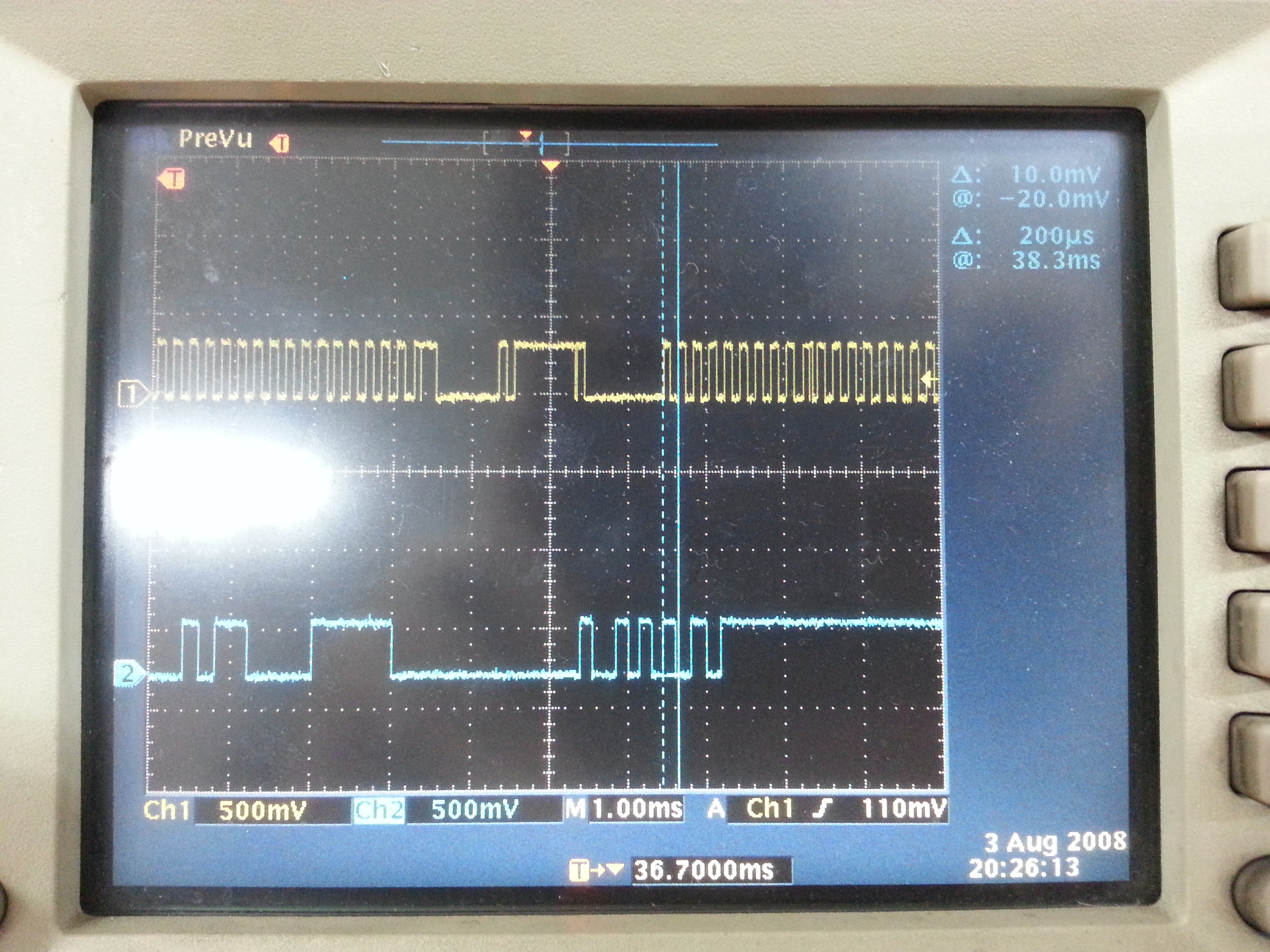
**yellow line is the clock line.

(Maybe it is because of the softDevice... I should make the pulse during BLE connection)

I read some post that I need to make the timer interrupt with GPIOTE, but I don't know how to make the timer interrupt with GPIOTE.

Can you fix my code up, or let me know some examples?

This is my code.

Thanks.


void timer2_init(void) {

uint32_t err_code;

// Configure timer
NRF_TIMER2->MODE      = TIMER_MODE_MODE_Timer;
NRF_TIMER2->BITMODE   = TIMER_BITMODE_BITMODE_16Bit;
NRF_TIMER2->PRESCALER = 4;


// Clear the timer
NRF_TIMER2->TASKS_CLEAR = 1;
NRF_TIMER2->CC[0] = 100;

NRF_TIMER2->INTENSET = TIMER_INTENSET_COMPARE0_Enabled << TIMER_INTENSET_COMPARE0_Pos;
NRF_TIMER2->SHORTS=(TIMER_SHORTS_COMPARE0_CLEAR_Enabled << TIMER_SHORTS_COMPARE0_CLEAR_Pos);
//NRF_TIMER1->TASKS_START = 1;

err_code = sd_nvic_SetPriority(TIMER2_IRQn,3);
APP_ERROR_CHECK(err_code);  

}

void TIMER2_IRQHandler(void) {

if ((NRF_TIMER2->EVENTS_COMPARE[0] == 1) && 
    (NRF_TIMER2->INTENSET & TIMER_INTENSET_COMPARE0_Msk))
{
    NRF_TIMER2->EVENTS_COMPARE[0] = 0;
    
    if(tick==0){
        nrf_gpio_pin_set(SCL);
        tick=1;    
    }
    else if(tick==1){
        nrf_gpio_pin_clear(SCL);
        tick=0;
        my_cnt++;  
    }  
}

//finish     
if(my_cnt==48){
  
    my_cnt=0;
    sd_nvic_DisableIRQ(TIMER2_IRQn);
    NRF_TIMER2->TASKS_STOP=1;
   
    nrf_gpio_pin_clear(SCL);   

}

}

static void my_app_timer_timeout_handler(void * p_context) {

 sd_nvic_ClearPendingIRQ(TIMER2_IRQn);
 sd_nvic_EnableIRQ(TIMER2_IRQn);  
 NRF_TIMER2->TASKS_START=1;
 nrf_gpio_pin_clear(SCL);

}

int main(void) {

// Initialize.
...
...

my_app_timer_init();
gpiote_init();
...
...
ble_stack_init();
scheduler_init();
...
...

my_app_timer_start();   //my_app_timer call the timer2 interrupt in every 20ms. 
advertising_start();
...
...
timer2_init();

// Enter main loop.
for (;;)
{
    app_sched_execute();
    power_manage();
}

}

  • Firstly, I believe: NRF_TIMER2->CC[0] = 100; should be: NRF_TIMER2->CC[0] = 99; as the counter counts from zero. Aside from that, I think that when the soft device is running, the timer interrupts may be delayed substantially, as the BLE stuff has to take priority. It is fairly easy to use events and tasks to generate rock-steady clock pulses(as the hardware handles everything), the only tricky thing will be how to stop at 48 pulses when the interrupts can get delayed by as much as your trace suggests. I notice you have referred to SCL in the code, so I assume this is being used in some capacity relating to I2C? If so, are you ignoring the SDA signal? Perhaps some better explanation of what you are trying to achieve will result in more useful answers.

  • Actually, It is not I2C, but it is similar to i2c. To be more specific SDA doesn't make signals according to the SCL.

    So I should make accurate SCL pulse.

  • Your comment does not help at all with understanding what you want to do. However, it seems to me that if you use a timer/counter to generate the clocks pulses by using a GPIO task linked to.timer compare events, you can probably also link the timer event(or another event from the same timer, i.e. another compare) to an increment task on another hardware counter timer, which would count up to 48 and then generate a compare event that would link to a task that stops the first timer. Not entirely sure if this would work, I'd try it if I didn't have work to do - it's exactly the sort of thing I find fascinating.

  • Hi

    I suspect the root of this delay in clock is that the CPU is not available to process the TIMER2 interrupt. This is because the softdevice blocks the CPU up to 6 ms during a radio event. The thing you can do is to avoid using the CPU for the generation of the clock. Do that by using PPI channels instead. That way you connect the TIMER2 event directly with GPIOTE task. You can see how that is done in the gpiote_example in the nRF51 SDK.

    You would have to use sd_* function to configure and set the PPI channels after you initialize the softdevice. You can see an example of that in the PWM library on Github, namely in the nrf_pwm.c file line 57

  • I don't understand how that could work. How are you going to get 96(assuming a gpiote toggle task) first channel compares before you get one second channel compare?

Related