This post is older than 2 years and might not be relevant anymore
More Info: Consider searching for newer posts

how to set up PWM dead time at the end of period

Hello,

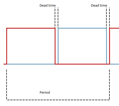
I use nrf52840 hardware FallingEdge polarity PWM (NRF_PWM0) , to generate 2 signals ~50% each (inverted). I do manage to set dead time between pulses in same period, but I cant set up dead at the end of each period (and i do fully undestand that it is impossible, acoording to PWM Specification Figure 2. PWM counter in up mode example - FallingEdge polarity).

But is there a way to set up a dead time around 120ns using Hardware PWM (NRF_PWMx)?

On figure below is what i want to achive.

Wasky
Parents
  • Yes; using Count Up Mode you require 2 x 4-word entries for each period, assuming you want a variable cycle length and up to 3 outputs. However if you switch to Dual Ramp Mode you only require a single 4-word entry for each period with Dead band between every pulse.

    //  DECODER.LOAD = Repeat
    //  =====================
    //   +----------------------------------> COMP0 OUT[0] Compare 0
    //   |         +------------------------> COMP1 OUT[1] Compare 1
    //   |         |         +--------------> COMP2 OUT[2] Compare 2
    //   |         |         |               (COMP3 OUT[3] Compare 3 not used)
    //   |         |         |        
    // +---------+---------+---------+---------+
    // | Compare | Compare | Compare | Top     | Cycle N
    // +---------+---------+---------+---------+
    // | Compare | Compare | Compare | Top     | Cycle N+1
    // +---------+---------+---------+---------+
    //                                 |
    //                                 +----> COUNTERTOP Cycle Period 4 steps, 1MHz clocks. Range 3-32767
    
    #define MAX_TOP   16096 // 4096 is 500uSec dual-ramp PWM at Prescaler div 1 - base clock frequency /1 -> 16MHz
    #define DEAD_BAND    8 // 8 is 1uSec dead band either side at Prescaler div 2 - base clock frequency /2 ->8MHz
    #define PHASE_HIGH   (DEAD_BAND+(MAX_TOP/2))
    
    // This table is designed to use the Loops mode
    nrf_pwm_values_wave_form_t PWM_LoopTable[] = {
      //   Index    PWM-1                   PWM-2           Other        Top Value
      //   =====    ======================  ==============  ===========  ============
      { /*   -  */  0x8000 | (PHASE_HIGH),   (PHASE_HIGH),         (0),  (MAX_TOP) }
    };
    
    .

    This is a sample, hope it helps

  • Thanks that should solve the problem, but i forgot o mention that i need to run same PWM (nrf_pwm0) on 2 different pins. So now the problem is that, if I invert outputs, it doenst work as i planed, because if I invert output pins, i'll get something like on figure below (NRF_PWM0, Red - pin 1, Blue - pin 2)


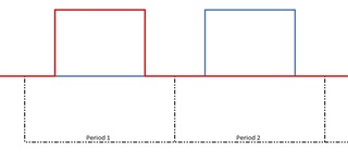
    If I use UpAndDown mode, i should get 2 signals in 2 different periods (figure below) but i cant invert them according to figure above. Or am I wrong? Should I somehow use SEQ[0] and SEQ[1]?

  • Can you clarify what you mean by two different pins and what you want to see on each pin? I thought you wanted non-overlapping 2-phase output on the two pins, such as for driving an H-Bridge motor or solenoid or piezo element. The dual-ramp I describe (or doubled single ramp up) does non-overlalpping 2-phase.

  • Yes, that's exactly that i want to achieve, non-overlapping 2 phase PWM on pins P0.17 and P0.15 (I want to drive V3205D BDD). I probably did not understood that example correctly. Is that an example from SDK? if yes, can can you please tell me wich one so I can check the whole code and understand how it works?

    Wasky

  • It's my code, but  started from an example I expect. There may be some good examples, worth a look. I use low-level drivers, but the setup is something like this:

    // Dual ramp PWM using Nordic library code
    static nrfx_pwm_t myPWM = NRFX_PWM_INSTANCE(0);
    
    void InitDualRampPWM(void)
    {
       uint32_t err_code;
       // Declare a configuration structure and use a macro to instantiate it with default parameters.
       nrfx_pwm_config_t pwm_config = NRFX_PWM_DEFAULT_CONFIG;
       // Configure PWM pins as outputs, and set to 0
       nrf_gpio_pin_clear(PIN_PWM_A);
       nrf_gpio_pin_clear(PIN_PWM_B);
       // Boost differential pwm driver pins to high drive if direct drive and not FET inputs
       nrf_gpio_cfg(PIN_PWM_A, NRF_GPIO_PIN_DIR_OUTPUT, NRF_GPIO_PIN_INPUT_DISCONNECT, NRF_GPIO_PIN_NOPULL, NRF_GPIO_PIN_H0H1, NRF_GPIO_PIN_NOSENSE);
       nrf_gpio_cfg(PIN_PWM_B, NRF_GPIO_PIN_DIR_OUTPUT, NRF_GPIO_PIN_INPUT_DISCONNECT, NRF_GPIO_PIN_NOPULL, NRF_GPIO_PIN_H0H1, NRF_GPIO_PIN_NOSENSE);
       // Override default PWM parameters:
       pwm_config.output_pins[0] = PIN_PWM_A;
       pwm_config.output_pins[1] = PIN_PWM_B;
       pwm_config.output_pins[2] = NRFX_PWM_PIN_NOT_USED;
       pwm_config.output_pins[3] = NRFX_PWM_PIN_NOT_USED;
    
       pwm_config.load_mode = NRF_PWM_LOAD_WAVE_FORM;     // Mode of loading sequence data from RAM: 3 == Use individual duty cycle for each PWM channel
       pwm_config.base_clock = PWM_PRESCALER_PRESCALER_DIV_16; // Prescaler - Base clock frequenc: 4 == /16, so 1MHz
       pwm_config.count_mode = PWM_MODE_UPDOWN_UpAndDown; // Operating mode of the pulse generator counter
       pwm_config.irq_priority = 6;                       // Interrupt priority
       pwm_config.step_mode = 0;                          // Decoder - Mode of advancing the active sequence: 0 = Sequence
       pwm_config.top_value = 10000; // 16-bit Value up to which the pulse generator counter counts: 3-32767, Not used in waveform mode
    
       // Pass config structure into driver init() function
       err_code = nrfx_pwm_init(&myPWM, &pwm_config, NULL);
       APP_ERROR_CHECK(err_code);
    }
    

    Look at the peripheral examples as well, there will be something there for PWM

Reply Children
No Data
Related