This post is older than 2 years and might not be relevant anymore
More Info: Consider searching for newer posts

Why don't I get a power on reset with this VDD >300mV increase?

Hello Devzone,

I'm designing a custom board solution that drives a motor using a nRF52832. The board is powered with 4 x AAA batteries and a 2.5V LDO (STLQ50C25R) is used to power the nRF52.

During high load with decently charged batteries the batteries voltage drops down to low voltages that the LDO can't regulate but which is still inside specification for the nRF52. In this example Vin and Vdd drops to around ~2.1V during load.

When the load decreases we see a 500-600mV spike on Vdd from the 2.1V level. This should easily cause an power on reset according to the product specification.

"A step increase in supply voltage of 300 mV or more, with rise time of 300 ms or less, within the valid supply range, may result in a system reset." Product Specification 1.4 page 82.

On 10x+ tested boards over many samples we have not seen the reset. The question is why have we not seen this?

The quick fix that I have available right now for this batch of boards would be to switch the LDO to one that outputs 1.8V (STLQ50C18R) but that feels a bit on the edge of the Vdd specification so I would like to keep the 2.5V one if possible.

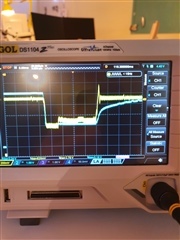
Attaching scope below. Not the best quality but it should help to understand the picture.

Yellow trace is the VDD. It starts at 2.5V and goes down to roughly 2.1V. Blue trace is battery voltage. It starts at 5.2V and goes down to roughly 2.1V as well. The time from the Vdd decrease until it increases is roughly 20ms.

Thanks for the help!

  • Do you want a reset?

    How are you detecting whether it has reset or not?

    I think that the operative word here is "may". The specification warns you that you may experience a reset on fast rising times for supply voltage.

    There are many components that will perform outside of specification, just don't count on it if the behaviour is vital.

    You might want to consider adding some ballast caps, these will help with the spike in power draw and as a side effect also slow down the power rail recovery.

    I can't tell from your image what times you are getting, nor which trace pertains to the Nrf52 power rail.

  • Hi CBD,

    I don't want a reset. The reset is detected by checking the movement of the motor. If the device resets the movement stops.

    Testing the boards that I have everything works just fine without reset but since it's outside of specification testing a few boards don't really give that much confidence that I can't happen later.

    Is there any more guidance or information on how to interpret the may reset? 

    Yellow trace is the VDD. It starts at 2.5V and goes down to roughly 2.1V. Blue trace is battery voltage. It starts at 5.2V and goes down to roughly 2.1V as well. The time from the Vdd decrease until it increases again is roughly 20ms.

    Caps for handling this would have to be unreasonable large unfortunately.


  • You can have your code check the reset register on power up, but this can be unreliable in brown out conditions.

    Another means to see through testing if a reset occurs would be to use a gpio pin to pull a line held high through a high value resistor to ground. 

  • Hi, the "may reset", means that there is a possibility that the device will reset. There will be chip to chip variations so the sensitivity will be different, but 300mV within 300ms is safe. In other words, designing a system where you can have more than 300mV voltage step within 300ms is the same as designing a system which is outside of spec. If you design a system that is outside of spec, you might get unwanted behavior. In this case you might get a reset.

    You can safely run the chip on 1.8V. The minimum recommended operating voltage is 1.7V, so to me that sounds like a better solution.

    I'm a bit concerned that the batteries are too small for the application? If you have 4x AAA in series and the voltage drops to 2.1V that’s close to 0.5V over each cell, which is pretty low. Is the current draw within the battery spec?

  • Hi Stian,

    Thanks for clarifying. The max current draw should be 700mA according to datasheet (not measured myself).

    We've been using non-brand name AAAs and it looks like the impedance increases fast when the battery gets discharged. More then a brand-name battery does I would guess.

    Since I can't control the brand of battery the customer uses I will look into using 1.8V instead which should be safer.

Related