This post is older than 2 years and might not be relevant anymore
More Info: Consider searching for newer posts

nRF9160 External Antenna circuit modifications

I have an application  where I will require an external antenna as our product sits in a metal enclosure.

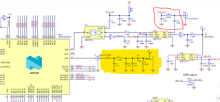
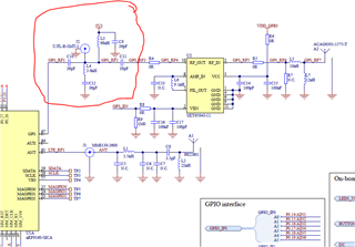
The example NRF91 DK development board shows a UFL connector (which the manual says can be used for testing and external antenna connection), but it also has provision for an internal antenna (which I am not interested in for my design – highlighted in yellow).


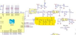
Can all of the highlighted items be removed if I use an external antenna (connected directly to the ANT pin via a UFL connector)?

Also, with regards to the GPS connection, I am not interested in a GPS connection - what provision do I have to make on my PCB for a N/C of this pin on my board?

Kind regards

Michael

Parents
  • Hi Andreas

    Thanks for the information. 

    With regards to the GPS, initially I don't think I want to use the GPS connection - so as you say I can leave the pin floating.

    Howvwer, If I did want to use it (for future proofing) what options are avaialable for use with an external antenna (due to me metal box)? By that I mean :

    a) If I use an external antenna connected to the GPS port (via a UFL connector), what would the PCB hardware requirements be. I take it I will still need the QM14501 (LNA + SAW filter), and then leave out the RF switches (QM13132s) (while we are discussing these, may I ask why are there two RF switches (QM13132s) connected to the GPS and not one)?

    b) I did hear some time ago  that it may be possible to use the same RF antenna for GPS location (multiplexed)...... is this correct/possible??

    Kind regards and thanks for the support.

    Michael

  • Hi Michael,


    a) The configuration for the external antenna depends a bit on the external antenna you will be using.

    • Passive external antenna: You can do without an LNA (U3), but this will likely give you some performance boost. The need of a SAW filter depends on the isolation between the LTE antenna and the GPS antenna, and how much intermodulated emissions there are from the GPS antenna when the modem transmits. Some LNAs also have a filter built in, eliminating the need for a SAW filter. The schematic you snipped show a different solution, using RF switches instead to disconnect the GPS antenna when the GPS is not used.
    • Active internal antenna: Being active, this has a LNA built in and will give the best performance as the LNA is as close to the antenna as possible. You do not need an LNA on the PCB in this case, but will need a bias-T to supply the antenna LNA:

      From DK v0.10.0:

    b) Yes, this is possible, e.g. as done in our Thingy91:

    This is not ideal though, it is hard to get a wideband enough antenna to support both LTE and GPS, at least PCB antenna, external might be easier. There is also a lot of loss between the antenna and LNA, meaning GPS performance will be further degraded.

    You could also route the GPS signal to the ANT pin, out through the AUX pin and into the GPS pin. Description here: https://infocenter.nordicsemi.com/topic/nwp_033/WP/nwp_033/nwp_033_intro.html?cp=14_0

    Last solution could be to find a 'N-in-1 antenna' that has separate connectors, but the antenna itself is one 'box'. There are probably a vast range of different types that support different bands, but this illustrates what I was thinking about: https://www.taoglas.com/product/adhesive-antenna-designed-for-use-on-metal/ They are probably relatively expensive, but this will probably give the best performance of all the same antenna alternatives.


    Best regards,

    Andreas

  • Very Informative - Thanks Andreas for your help and expert advise on this subject

    Cheers

    Michael

Reply Children
No Data
Related