This post is older than 2 years and might not be relevant anymore
More Info: Consider searching for newer posts

Voltage at PPK without external supply

We have our first prototype ready and were measuring the power consumption. During development the values seems to be wrong.

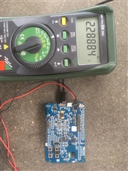
So I just added a voltmeter to the DUT out clamps and put the switch into external position. Surprisingly I measured 2,28 V. How could that be? No external supply was present? Even when I put a 3 V supply to the "External supply" I measured 2,28V? Where does this voltage come from? In my opinion there should be noting?

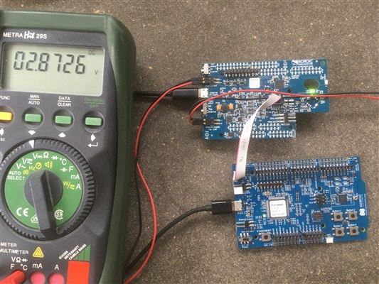
The second try was to disconnect the DK from the PPK. I connected the two board with a 10pin flat cable, soldered the SB32 on the DK to switch to the external device, and supplied 3,2V from external. The output of "External DUT" was always 2,8V. 

Thanks for your help.

Parents
  • Hi, you need to run the PPK software at the same time as you are measuring the voltage. The PPK software is configuring the PPK correctly.

    The voltage on the DK is 2.8V because of the reverse voltage protection diodes on the DK. So in DK mode, you should see 2.8V on the DUT output.

    The external regulator is not working properly when the PPK is stacked on top of the DK. Use it in standalone mode as you are showing in your first picture. This setup should work properly once you start the PPK software.

Reply
  • Hi, you need to run the PPK software at the same time as you are measuring the voltage. The PPK software is configuring the PPK correctly.

    The voltage on the DK is 2.8V because of the reverse voltage protection diodes on the DK. So in DK mode, you should see 2.8V on the DUT output.

    The external regulator is not working properly when the PPK is stacked on top of the DK. Use it in standalone mode as you are showing in your first picture. This setup should work properly once you start the PPK software.

Children
Related