This post is older than 2 years and might not be relevant anymore
More Info: Consider searching for newer posts

Doubts about programming

Hello.
I'm having problems to programme the nRF52832.
I'm just connecting the VCC (+3,3V), GND and SWDIO and SWDCLK.
Is it ncessary to connect any other devices like capacitors or reset pins in the circuit?
My problem is with programming process... I'm not beeing able to receive a "success" from the programming process.

I'm using the devkit nRF52-DK as programmer.
So I connecting the VDD (3V) pin (of P1 connector) to VTG (of P20 connector).
I connecting the GND pin (of P1 connector) to GND detect (of P20 connector).
And connecting VDD, GND (of P1 connector) to my board application. And connectiong SWDIO and SWDCLK (of connector P1) to my board application too.

This process occour very well with other boards that I bought few weeks ago (that are full assempbled but now, I'm tryng to do it in my application and it don't occour.
I'm not sure if is necessary to fill (solder) the PCB with all components to able the programming... because I believe that is necessary just the nRF and power supply.


Thank you.

  • Hi

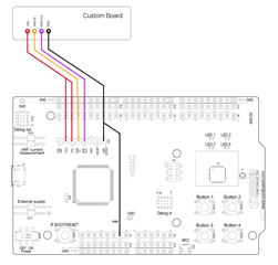
    It shouldn't be necessary to do anything different when your program an nRF52 the first time. Please make sure that your custom board is connected to the DK like in the picture below. I'd also like to see the schematics of your custom board so I can see that everything is connected correctly. If you don't want to share your schematic files publicly, please say so, and I will set this case to private mode so that only yourself and Nordic engineers will be able to see this case.

    Best regards,

    Simon

  • These jumpers are exacltly how I'm trying to programm the nRF52.
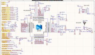
    And bellow follows my circuit. It is very similar with reference design.
    The marking code of the nRF that I'm using is "N52832 QFAA E1" (that I can't program). But I have other custom board with "N52832 QFAA E0" that I can program very well... Is there any diference related with this "E0" and "E1"?

  • Hi

    There shouldn't be any differences between the E0 and E1 build codes, these codes are just to track which supplier has manufactured the IC. Are the E0 and E1 connected identically HW-wise? On your schematics, there are some components that are crossed out in red, does that mean that they're not mounted? If so, I think you should mount L2 and L3 in your DCDC circuit. Are R28 and R29 just shorted, as SWDIO and SWDCLK need to reach the chip somehow?

    Best regards,

    Simon

  • I've readed again the datasheet and I noted one thing that I haven't noted before...
    I placed these periferical componentes in the opossite side of PCB (the nRF is in the top and the capacitors are in the bottom).
    They are very close of respective nRF pins, but in opposite side of PCB.
    I believe that it can be the reason for can't program it...
    What do you think? Is it possible?

  • Anderson Silva said:
    I placed these periferical componentes in the opossite side of PCB (the nRF is in the top and the capacitors are in the bottom).

     I'm sorry, but what do you mean by this? Have you connected the components that should go on one side of the board to the other, I.E. left to right and vice versa? In that case, this is definitely the reason you're having trouble. If your nRF chip is on the wrong way, please try to desolder it and place it correctly.

    Best regards,

    Simon

Related