This post is older than 2 years and might not be relevant anymore
More Info: Consider searching for newer posts

Doubts about programming

Hello.
I'm having problems to programme the nRF52832.
I'm just connecting the VCC (+3,3V), GND and SWDIO and SWDCLK.
Is it ncessary to connect any other devices like capacitors or reset pins in the circuit?
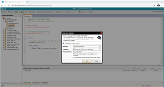
My problem is with programming process... I'm not beeing able to receive a "success" from the programming process.

I'm using the devkit nRF52-DK as programmer.
So I connecting the VDD (3V) pin (of P1 connector) to VTG (of P20 connector).
I connecting the GND pin (of P1 connector) to GND detect (of P20 connector).
And connecting VDD, GND (of P1 connector) to my board application. And connectiong SWDIO and SWDCLK (of connector P1) to my board application too.

This process occour very well with other boards that I bought few weeks ago (that are full assempbled but now, I'm tryng to do it in my application and it don't occour.
I'm not sure if is necessary to fill (solder) the PCB with all components to able the programming... because I believe that is necessary just the nRF and power supply.


Thank you.

  • No no....
    The electrical connections are OK. The componentes are placed in correct positions.
    But the datasheet recomends to put the nRF in the TOP face and the periferal componentes in the TOP too (as close as possible of respecitive pins).
    But I've done the layout with this periferal devices in the BOTTON face.... and the nRF are in the TOP face... So the electrical connections are right. There's no electrical mistakes... All the connections cross the PCB (by vias) from nRF (in the top) to perifecical devices (in the botoon)...
    I just haven't followed the recommended layout.
    But I'm not sure if it would cause the problem with programming procedure...
    Do you think that it could be the reason?

  • Hi Anderson

    As long as the components still are as close as possible to the board pins moving them to the other side of the board shouldn't be detrimental for your design. Do you mind uploading the Gerber files of your design so I can confirm whether or not your design is the problem?

    Best regards,

    Simon

  • Hi Simonr
    These are the Gerber Files.
    As you can see I've placed the componentes as close as possible from the respective pins. But I've placed in the othe PCB face...
    But I didn't imagined that it could cause the problem with programming process....
    Actually I'm still not so sure if this is the problemm...
    I believe that it could cause problems with performance or something related with Bluetooth... But not with programming process...
    Thanks for your help.
    PCB_Nordic.zip

  • Hi

    After looking at your layout, can you tell me whether the resistors R28 and R29 are mounted or not? Why are the SWCLK and SWDIO pins connected to the 3V3 net via these resistors? When programming these pins should only be connected to the SWD pins on the debugger and not have a voltage on them. The external chip must be powered itself, but not the SWD pins.

    Best regards,

    Simon

  • Hi Simonr.
    Thank you so much for your help.
    These resistors (R28 and R29) are not mounted. We put them in the circuit just to imagining (preventing) if these would be necessary pull ups... But after manufacture the PCB we confirm that wasn't necessary.
    But we realised what was the problem yesterday and fix it. All the PCB had a problem in the conection from some pads (in top layer) and midlayer (intermitente conection). So we manufactor another PCB and it worked very well.
    Thank you very much for your help. With you w could filter and aliminate problems till find the real problem.

    Now I wish to ask you another question...
    Is it possible to create a simple "HelloWorld" code in MBED and program the Nordic with J-LINK?
    I'm asking you it because I've created a code to blink a led but it doesn't blink the led.
    I've created a new program in MBED using Nordic nRF52-DK with template "(mbed OS 5)Blink LED HelloWorld" as you can see in the images bellow.
    And I'm trying to blink the a led connected to pin P0.28 in my PCB. But it doens't works. I've already confirmed that led circuit works.
    In the Nordic Dev Kit (nRF52-DK) this program works very well (using the pins P0.17 ~ P0.20)... But in the PCB it doesn't works... So I believe that probably MBED just Works with Dev Kit.
    Is it correct?

    Thank you very much again.
    Anderson


Related