This post is older than 2 years and might not be relevant anymore
More Info: Consider searching for newer posts

Problem of 52832 SPI interface

Hi,

I have a problem of 52832's SPI interface. Please find following description:

1. My test code is come from "spi" example code, by modify the SPI ping setting (please find sdk_config.h) and NRF_DRV_SPI_DEFAULT_CONFIG in nrf_drv_spi.h, please find following attach file

Test_SPI.7z

#define NRF_DRV_SPI_DEFAULT_CONFIG                           \
{                                                            \
    .sck_pin      = NRF_DRV_SPI_PIN_NOT_USED,                \
    .mosi_pin     = NRF_DRV_SPI_PIN_NOT_USED,                \
    .miso_pin     = NRF_DRV_SPI_PIN_NOT_USED,                \
    .ss_pin       = NRF_DRV_SPI_PIN_NOT_USED,                \
    .irq_priority = SPI_DEFAULT_CONFIG_IRQ_PRIORITY,         \
    .orc          = 0xFF,                                    \
    .frequency    = NRF_SPI_FREQ_500K,                     \
    .mode         = NRF_DRV_SPI_MODE_2,                      \
    .bit_order    = NRF_DRV_SPI_BIT_ORDER_MSB_FIRST,         \
}

2. There have four 4.7K pull-up register between SPI CS, CLK, MOSI, MISO and Vcc.

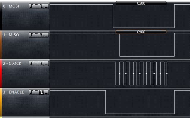
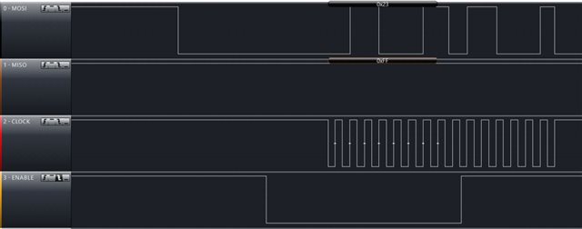
Following screen is the SPI wave-form when the program send one byte to SPI interface.  There have two problem in following screen.

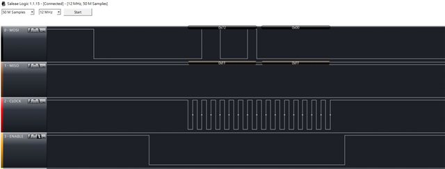
a. The sending data is ASCII '1', it's hex code is 0x31.  but the data which get from  “Logic analyzer" get "0x72" in MOSI pin. why?

b. The program only send one byte data, but "Logic analyzer" had found 2 byte data "0x72 and 0x00" in MOSI, there also have 16 clock in CLK pin.

Would you please tell me how to fix this problem?

Thank you,

Chianglin

Parents
  • Hi,

    a) are you sure that your default config is taken from the right file? Your SCK pin behaves as in mode 1 - data is shifted with leading edge, sampling is expected at trailing one.

    b) you're initializing uint8_t[] array with a string. Most compilers will give you an error here, but if your compiler didn't, it takes a sting as two bytes - including trailing zero character. The right way is: 

    static uint8_t m_tx_buf[1]  = { '1' };

  • Hi,

    a) My default SCK pin in sdk_config.h setting is:

    #ifndef SPI_SCK_PIN
    #define SPI_SCK_PIN 14
    #endif

      And my initialize setting in main() is:

        nrf_drv_spi_config_t spi_config = NRF_DRV_SPI_DEFAULT_CONFIG;
        spi_config.ss_pin   = SPI_SS_PIN;
        spi_config.miso_pin = SPI_MISO_PIN;
        spi_config.mosi_pin = SPI_MOSI_PIN;
        spi_config.sck_pin  = SPI_SCK_PIN;
        APP_ERROR_CHECK(nrf_drv_spi_init(&spi, &spi_config, spi_event_handler, NULL));

      NRF_DRV_SPI_DEFAULT_CONFIG is:

    #define NRF_DRV_SPI_DEFAULT_CONFIG                           \
    {                                                            \
        .sck_pin      = NRF_DRV_SPI_PIN_NOT_USED,                \
        .mosi_pin     = NRF_DRV_SPI_PIN_NOT_USED,                \
        .miso_pin     = NRF_DRV_SPI_PIN_NOT_USED,                \
        .ss_pin       = NRF_DRV_SPI_PIN_NOT_USED,                \
        .irq_priority = SPI_DEFAULT_CONFIG_IRQ_PRIORITY,         \
        .orc          = 0xFF,                                    \
        .frequency    = NRF_SPI_FREQ_500K,                     \
        .mode         = NRF_DRV_SPI_MODE_2,                      \
        .bit_order    = NRF_DRV_SPI_BIT_ORDER_MSB_FIRST,         \
    }

      If I want to create following wave form, how can I modify my program?

    b) I had modify my program by using your suggest method, please fine following program,

    static uint8_t       m_tx_buf[1] = {'1'}
    
    APP_ERROR_CHECK(nrf_drv_spi_transfer(&spi, m_tx_buf, 1, m_rx_buf, 1));

     but, I found following wave-form output in Logic-analyzer.

      The wave-form still not correct (output data and output length). 

      Would you please give me some suggestion?

    Thank you

Reply Children
Related