Question/Problem Statement
For evaluation we decided to do some current measurements using the power profiler kit. As a benchmark run, we wanted to measure the current on nRF52832 DK board with the setup described below. Somehow, the 832 doesn't turn on, because VDD_DUT is regulated to 1.5V. Why is this? How could we fix this to ensure VDD_DUT follows our supply voltage? We clearly missed something, but I cannot figure out what it is.
Setup
- External Supply ranging from 1.8V - 3.3V;
- External Debugger connected to the power profiler;
- Power profiler configured as:
- Power select (SW4) set to external;
- External supply set in the range 1.8V - 3.3V;
- DUT select (SW2) set to DK;
- nRF52832 DK configured as:
- Supply set in the range 1.8 - 3.3V (same supply as for the ppk);
- SB5, SB6, SB7, SB8 are open, since those LEDs provided a current path to the nRF52832 chip, resulting in leakage current and the device not turning off;
- SB9 open;
- SB33, SB34, SB35 are open, not necessary when the USB is not plugged in, but otherwise the 3.3V regulator (U3) would overrule the 1.8V supply at P21;
- SB12 closed to bypass the input diode;
Results
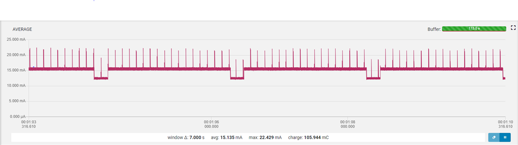
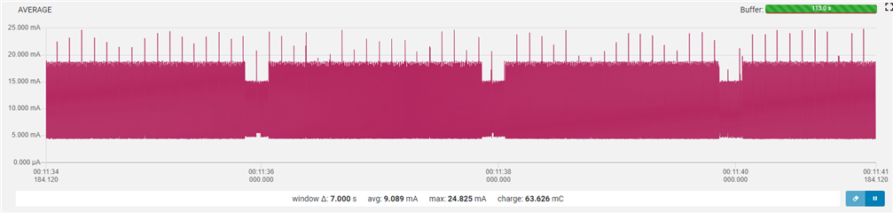
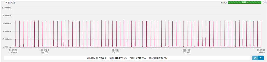
Now for the results,
- The 832 chip on the DK simply won't turn on. Whatever supply voltage we select in the range 1.8V to 3.3V the power profiler regulates the pin going to the DK to 1.54V. The current runs only through resistor R2, the other switches (U3 and U4) are open, hence no parallel path.
- The voltage drop across R2 + 1.54V = supply voltage.
- The power profiler is available and can be read with the nRF Connect SDK app.
- The atmega chip is in sleep mode, when pressing the reset, we see an increase in current of 5mA.
- A jumper across P22 enables the 832 and we see an increase of 7 mA in current (just a simple loop is programmed to the 832, nothing else);
- Insertion of the USB to the DK increases the supply current demand with a lot, think in the range 90mA;
Thanks in advance for your help!