
Hi.
I'm using nRF52832 with MPU9250 IMU sensor to gather accelerometer, gyroscope data for mobility.
MPU9250 sensor is connected to nRF52832 via I2C line.
When I use MPU9250 only, all the data is good. No bounce.
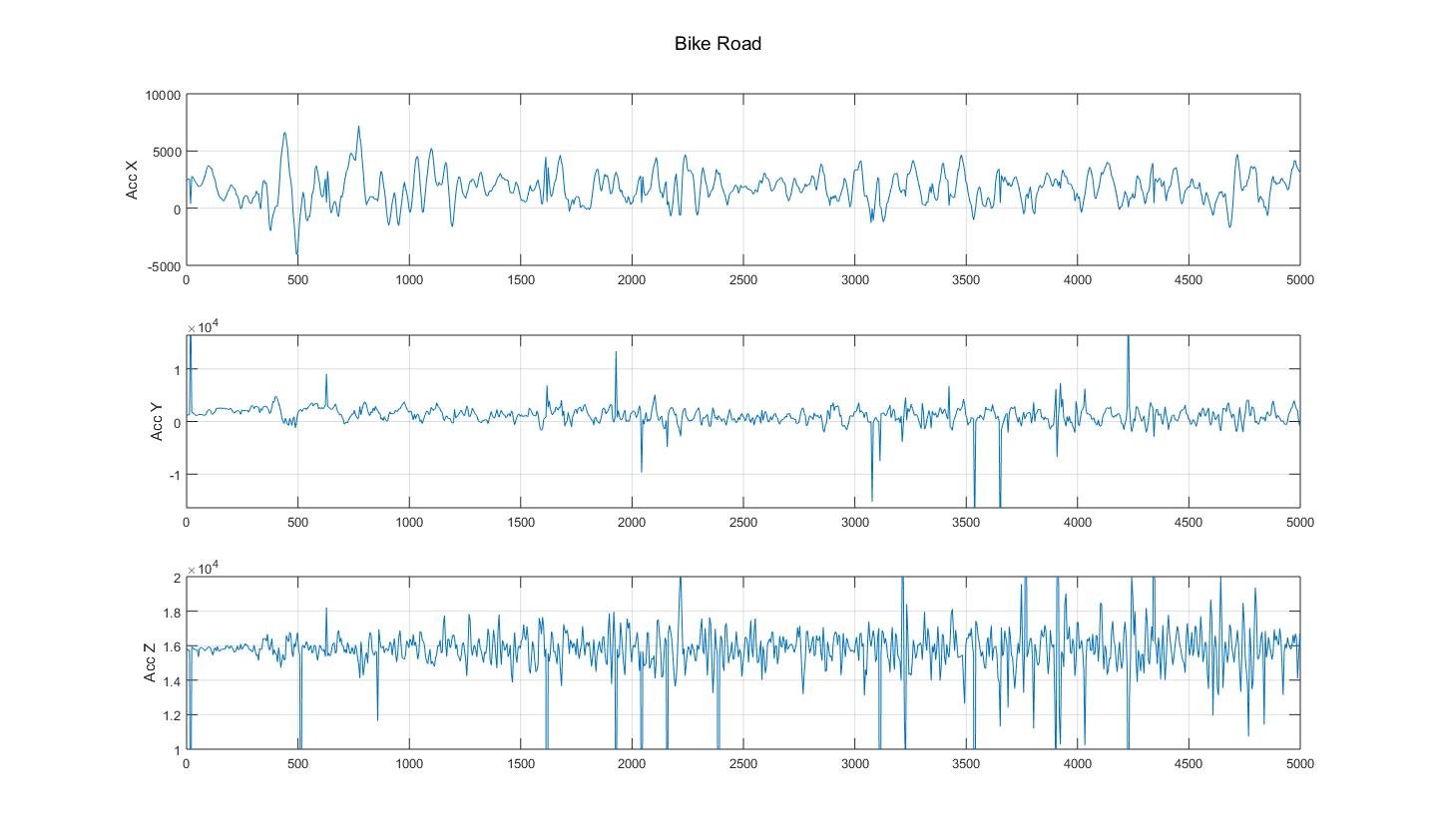
But after enable BLE UART, sensor data is bouncing irregularly.
Please look the graph.
And this is my source code to get the data from MPU9250 IMU sensor via I2C.
This is custom I2C library
void _Wire::begin(){
	// I2C 통신을 활성화 시키는 함수
	// 기본 통신 속도는 400kHz
	// 기본 설정 핀 : SCL(12번), SDA(11번)
	// 설정 핀은 Wire.h 에서 바꿀 수 있음

	// I2C 통신 비활성화
	NRF_TWI0->ENABLE = 0;

	// SCL/SDA핀 설정
	NRF_TWI0->PSELSCL = pinSCL;
	NRF_TWI0->PSELSDA = pinSDA;

	// 통신 주파수 설정(400kHz)
	NRF_TWI0->FREQUENCY = 0x06680000;

	// 인터럽트 비활성화
	NRF_TWI0->INTENCLR = 0x044286;

	// I2C 통신 활성화
	NRF_TWI0->ENABLE = 5;

	// 이벤트 초기화
	NRF_TWI0->EVENTS_RXDREADY = 0;
	NRF_TWI0->EVENTS_TXDSENT = 0;
}

uint8_t _Wire::requestFrom(uint8_t address, uint8_t bytes){
	// Slave device로부터 데이터를 요청하는 함수
	uint8_t recvLength = 0;

	// 통신 주소 및 Read 신호 송신
	NRF_TWI0->ADDRESS = address;

	NRF_TWI0->TASKS_STARTRX = 1;

	for(uint8_t i=0;i<bytes;i++){
		// Byte Boundary 이벤트 확인
		while(!NRF_TWI0->EVENTS_BB){}
		NRF_TWI0->EVENTS_BB = 0;

		// 마지막 데이터가 오면 STOP
		if(i == (bytes - 1)){
			NRF_TWI0->TASKS_STOP = 1;
		}

		// 데이터 읽기
		while(!NRF_TWI0->EVENTS_RXDREADY){}
		NRF_TWI0->EVENTS_RXDREADY = 0;
		rxBuffer[i] = NRF_TWI0->RXD;
	}

	return recvLength;
}

void _Wire::beginTransmission(uint8_t address){
	// TWI 데이터 전송을 시작하는 함수
	NRF_TWI0->ENABLE = 5;
	NRF_TWI0->ADDRESS = address;
	NRF_TWI0->TASKS_STARTTX = 1;
	memset(&rCount, 0x00, sizeof(rCount));
	memset(&rxBuffer, 0x00, sizeof(rxBuffer));
	rCount = 0;
}

uint8_t _Wire::endTransmission(bool toggle){
	// TWI 통신 종료 함수
	uint8_t err_code = 0;
	if(toggle){
		if(!NRF_TWI0->EVENTS_STOPPED){NRF_TWI0->TASKS_STOP = 1;}
		while(!NRF_TWI0->EVENTS_STOPPED){}
		NRF_TWI0->EVENTS_STOPPED = 0;
		err_code = 1;
	}
	NRF_TWI0->ENABLE = 0;
	return err_code;
}

uint8_t _Wire::write(uint8_t data){
	NRF_TWI0->TXD = data;
	while(!NRF_TWI0->EVENTS_TXDSENT){}
	NRF_TWI0->EVENTS_TXDSENT = 0;
	return 0;
}

uint8_t _Wire::available(){
	return 0;
}

uint8_t _Wire::read(){
	static uint8_t output = 0;
	output = rxBuffer[rCount];
	rCount++;
	return output;
}
This is MPU9250 custom library.
uint8_t _MPU9250::Init(){
	uint8_t err_code = 0;

	// TWI 통신 초기화 및 시작
	Wire.begin();

	// MPU9250 초기화
	writeData(DEVICE_ID, PWR_MGMT_1, 0x80);
	nrf_delay_ms(200);
	writeData(DEVICE_ID, PWR_MGMT_1, 0x00);

	// 자이로스코프와 온도센서의 DLPF 적용 값 설정
	setCfgDLPF(DLPF_GYRO_5HZ);

	// 가속도 센서 측정범위 및 DLPF 적용
	setCfgAcc(ACCEL_RANGE_2G, DLPF_ACC_5HZ, ACC_DLPF_ON);

	// 자이로스코프 측정범위 설정
	setCfgGyro(GYRO_RANGE_1000DPS, GYRO_DLPF_ON);

	// Bypass Mode 활성화
	writeData(DEVICE_ID, INT_PIN_CFG, 0x02);

	// 지자기 센서 모드 설정
	// 먼저 Fuse ROM Access 모드로 설정
	setMagMode(MAG_RESOLUTION_16BIT, MAG_FUSE_ROM_ACCESS_MODE);

	// ASA 데이터 읽기
	ASA = getMagASA();

	// Continuous 2 모드로 설정
	setMagMode(MAG_RESOLUTION_16BIT, MAG_CONTINUOUS2_MODE);

	return err_code;
}

uint8_t _MPU9250::writeData(uint8_t device, uint8_t addr, uint8_t data){
	// 레지스터에 값을 쓰는 함수
	uint8_t err_code = 0;

	// 통신 시작
	Wire.beginTransmission(device);
	Wire.write(addr);
	Wire.write(data);
	Wire.endTransmission(true);

	return err_code;
}


int16_t* _MPU9250::getRawAcc(){
	// 가속도 센서 Raw 데이터 읽기 함수
	static int16_t output[3];
	Wire.beginTransmission(DEVICE_ID);
	Wire.write(ACCEL_XOUT_H);
	Wire.requestFrom(DEVICE_ID, 6);
	for(uint8_t i=0;i<3;i++){
		output[i] = Wire.read() << 8 | Wire.read();
	}
	Wire.endTransmission(true);
	return output;
}

int16_t* _MPU9250::getRawGyro(){
	// 자이로스코프 Raw 데이터 읽기 함수
	static int16_t output[3];
	Wire.beginTransmission(DEVICE_ID);
	Wire.write(GYRO_XOUT_H);
	Wire.requestFrom(DEVICE_ID, 6);
	for(uint8_t i=0;i<3;i++){
		output[i] = Wire.read() << 8 | Wire.read();
	}
	Wire.endTransmission(true);
	return output;
}
