
Hi. I've developed a PCB with nRF52832 and I'm having problems with the circuit. When I put my hands closelly of P0.00(XL1) and P0.01(XL2) the bahavior of nRF changes... I'm not using external crystal in these pins. I'm using then as IO's. P0.00 as output and P0.01 a input
Does anyone have any idea of what is happening?
I've done the layout a little bit different of what was suggested by the datasheet... Could it be the reason? Or maybe the configuration of oscilator?
The circuit SCH and some prints of PCB are showed bellow.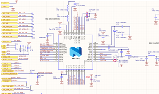
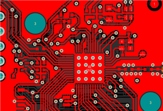 top layer
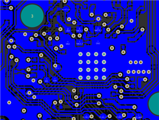 bottom layer

