This post is older than 2 years and might not be relevant anymore
More Info: Consider searching for newer posts

Timeslot / Radio signal callback hander sometimes called with 10us delay

In a project based on Softdevice S132 7.0.1 employing the Softdevice timeslot API, I noticed that the nrf_radio_signal_callback_t function passed into sd_radio_session_open() sometimes seems to be invoked with a 10us delay compared to other occasions. I'm not sure whether this pertains to all signals handled by the callback; so far I looked at NRF_RADIO_CALLBACK_SIGNAL_TYPE_RADIO.

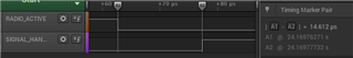
The following diagram shows the timing as recorded with debug pins The "RADIO_ACTIVE" signal is two PPI channels linking the NRF_RADIO->EVENTS_READY event with a GPIOTE task and the NRF_RADIO->EVENTS_DISABLED event with another GPIOTE task on the same pin. The "SIGNAL_HANDLER" signal is a software-toggled pin at the beginning of the signal handler. This is the slower timing.

With "faster timing" the same event looks like this:

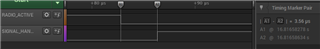
As you can see, it takes 14.612us between NRF_RADIO->EVENTS_DISABLED being asserted and the signal handler being called if no debugger is connected, while it only takes 3.56us if none is connected.

I had a hunch that it might be somewhat related to the issue NUS connection problems with TimeSync example ported to SDK16.0.0 so I tried to configure the timeslot with NRF_RADIO_HFCLK_CFG_NO_GUARANTEE, but this does not seem to have any impact.

Initially, I thought it is related to the debugger being connected or not, but currently I'm not sure. I have not run into any issues with the debugger connected, but without debugger connected the scenario with 10us delay seems to occur from time to time.

How can I ensure that the delay is always smaller?

EDIT: I invested some more time in investigating this issue and realised that it is not related to timeslot use. Measuring the same timings with a project, that does not have the softdevice enabled, but uses the radio directly; I noticed that sometimes there is a factor 10 delay between the peripheral event and the IRQ handler being called. I'm testing on a nRF52832 (on the PCA10040 / nRF52 DK)

EDIT 2: Further investigation showed that the faster timing is obsorvable significantly more often than the slower timing if a debugger is connected. The slower timing is observable significantly more often if no debugger is connected. It seems like whether the radio is receiving or transmitting does not have an impact on the outcome.

Parents
  • Hi Michael, 

    The 10us delay extra is most likely the time it take for the CPU to wake up from system ON IDLE. Did you put the CPU to sleep (IDLE) ? 

    When the debugger is connected the CPU is kept running all the time (including the HFCLK). This explain why you have shorter latency. 

    But 3.5 us is a little bit long from my experience. 

    I was using the following code and can see 0.5us latency if I don't put the CPU to sleep about 11.8us if I put the CPU to sleep (with the __WFE and __SEV).  

    #include <nrf.h>
    #include "nrf_delay.h"
    #define PPI_CHANNEL (0)
    #define PIN_GPIO    (17)
    #define PIN_GPIO2    (18)
    void RADIO_IRQHandler(void)
    {
        if (NRF_RADIO->EVENTS_DISABLED)
        {
            NRF_GPIO->OUTCLR = (1UL << PIN_GPIO2);  
            NRF_RADIO->EVENTS_DISABLED=0;
        }
      /*  if (NRF_RADIO->EVENTS_READY )
        {
            NRF_GPIO->OUTSET = (1UL << PIN_GPIO2);  
            NRF_RADIO->EVENTS_READY=0;
         }
        */
    
     }
    int main(void)
    {
      // Packet to send
      uint8_t packet[16] = "demopacket";
      
      // Start HFCLK from crystal oscillator. The radio needs crystal to function correctly.
      NRF_CLOCK->TASKS_HFCLKSTART = 1;
      while (NRF_CLOCK->EVENTS_HFCLKSTARTED == 0);
      
      // Configure radio with 2Mbit Nordic proprietary mode
      NRF_RADIO->MODE = RADIO_MODE_MODE_Nrf_2Mbit << RADIO_MODE_MODE_Pos;
      
      // Configure packet with no S0,S1 or Length fields and 8-bit preamble.
      NRF_RADIO->PCNF0 = (0 << RADIO_PCNF0_LFLEN_Pos) |
                         (0 << RADIO_PCNF0_S0LEN_Pos) |
                         (0 << RADIO_PCNF0_S1LEN_Pos) | 
                         (RADIO_PCNF0_S1INCL_Automatic << RADIO_PCNF0_S1INCL_Pos) |
                         (RADIO_PCNF0_PLEN_8bit << RADIO_PCNF0_PLEN_Pos);
      
      // Configure static payload length of 16 bytes. 3 bytes address, little endian with whitening enabled.
      NRF_RADIO->PCNF1 =  (16 << RADIO_PCNF1_MAXLEN_Pos) |
                          (16 << RADIO_PCNF1_STATLEN_Pos) |
                          (2  << RADIO_PCNF1_BALEN_Pos) | 
                          (RADIO_PCNF1_ENDIAN_Little << RADIO_PCNF1_ENDIAN_Pos) |
                          (RADIO_PCNF1_WHITEEN_Enabled << RADIO_PCNF1_WHITEEN_Pos);
      
      // initialize whitening value
      NRF_RADIO->DATAWHITEIV = 0x55;
      
      // Configure address Prefix0 + Base0
      NRF_RADIO->BASE0   = 0x0000BABE;
      NRF_RADIO->PREFIX0 = 0x41 << RADIO_PREFIX0_AP0_Pos;
      
      // Use logical address 0 (BASE0 + PREFIX0 byte 0)
      NRF_RADIO->TXADDRESS = 0 << RADIO_TXADDRESS_TXADDRESS_Pos;
      
      // Initialize CRC (two bytes)
      NRF_RADIO->CRCCNF = (RADIO_CRCCNF_LEN_Two << RADIO_CRCCNF_LEN_Pos) |
                          (RADIO_CRCCNF_SKIPADDR_Skip << RADIO_CRCCNF_SKIPADDR_Pos);
      NRF_RADIO->CRCPOLY = 0x0000AAAA;
      NRF_RADIO->CRCINIT = 0x12345678;
      
      // Enable fast rampup, new in nRF52
      NRF_RADIO->MODECNF0 = (RADIO_MODECNF0_DTX_B0 << RADIO_MODECNF0_DTX_Pos) |
                            (RADIO_MODECNF0_RU_Fast << RADIO_MODECNF0_RU_Pos);
                            
      // 0dBm output power, sending packets at 2400MHz
      NRF_RADIO->TXPOWER = RADIO_TXPOWER_TXPOWER_0dBm << RADIO_TXPOWER_TXPOWER_Pos;
      NRF_RADIO->FREQUENCY = 0 << RADIO_FREQUENCY_FREQUENCY_Pos;
      
      // Configure address of the packet and logic address to use
      NRF_RADIO->PACKETPTR = (uint32_t)&packet[0];
      
      // Configure shortcuts to start as soon as READY event is received, and disable radio as soon as packet is sent.
      NRF_RADIO->SHORTS = (RADIO_SHORTS_READY_START_Enabled << RADIO_SHORTS_READY_START_Pos) |
                          (RADIO_SHORTS_END_DISABLE_Enabled << RADIO_SHORTS_END_DISABLE_Pos);
                          
                          
      NRF_GPIO->DIRSET = (1UL << PIN_GPIO);
      
      // Configure GPIOTE->TASKS_OUT[0] to toggle PIN_GPIO
      NRF_GPIOTE->CONFIG[0] = (GPIOTE_CONFIG_MODE_Task       << GPIOTE_CONFIG_MODE_Pos) |
                              (GPIOTE_CONFIG_OUTINIT_Low     << GPIOTE_CONFIG_OUTINIT_Pos) |
                              (GPIOTE_CONFIG_POLARITY_Toggle << GPIOTE_CONFIG_POLARITY_Pos) |
                              (PIN_GPIO                      << GPIOTE_CONFIG_PSEL_Pos);   
    
      NRF_GPIO->DIRSET = NRF_GPIO->DIRSET|1UL << PIN_GPIO2;
      NRF_GPIO->PIN_CNF[PIN_GPIO2] = (GPIO_PIN_CNF_DIR_Output << GPIO_PIN_CNF_DIR_Pos) |
                                    (GPIO_PIN_CNF_DRIVE_S0S1 << GPIO_PIN_CNF_DRIVE_Pos) |
                                    (GPIO_PIN_CNF_INPUT_Connect << GPIO_PIN_CNF_INPUT_Pos) |
                                    (GPIO_PIN_CNF_PULL_Disabled << GPIO_PIN_CNF_PULL_Pos) |
                                    (GPIO_PIN_CNF_SENSE_Disabled << GPIO_PIN_CNF_SENSE_Pos);
      // Configure GPIOTE->TASKS_OUT[0] to toggle PIN_GPIO
      
      NRF_PPI->CH[PPI_CHANNEL].EEP = (uint32_t)&NRF_RADIO->EVENTS_DISABLED ;
      NRF_PPI->CH[PPI_CHANNEL].TEP = (uint32_t)&NRF_GPIOTE->TASKS_OUT[0];
      
      // Enable PPI channel
      NRF_PPI->CHENSET = (1UL << PPI_CHANNEL);
      
      NVIC_ClearPendingIRQ(RADIO_IRQn);
      NVIC_EnableIRQ(RADIO_IRQn);  
      NRF_RADIO->INTENSET      = RADIO_INTENSET_DISABLED_Msk;    
    
      // Continuously send the same packet
      while (1)
      { 
        NRF_RADIO->TASKS_TXEN = 1;
        NRF_GPIO->OUTSET = (1UL << PIN_GPIO2);  
        /*__SEV();
        __WFE();
        __WFE();*/
        
        nrf_delay_ms(500);
      }
    }

Reply
  • Hi Michael, 

    The 10us delay extra is most likely the time it take for the CPU to wake up from system ON IDLE. Did you put the CPU to sleep (IDLE) ? 

    When the debugger is connected the CPU is kept running all the time (including the HFCLK). This explain why you have shorter latency. 

    But 3.5 us is a little bit long from my experience. 

    I was using the following code and can see 0.5us latency if I don't put the CPU to sleep about 11.8us if I put the CPU to sleep (with the __WFE and __SEV).  

    #include <nrf.h>
    #include "nrf_delay.h"
    #define PPI_CHANNEL (0)
    #define PIN_GPIO    (17)
    #define PIN_GPIO2    (18)
    void RADIO_IRQHandler(void)
    {
        if (NRF_RADIO->EVENTS_DISABLED)
        {
            NRF_GPIO->OUTCLR = (1UL << PIN_GPIO2);  
            NRF_RADIO->EVENTS_DISABLED=0;
        }
      /*  if (NRF_RADIO->EVENTS_READY )
        {
            NRF_GPIO->OUTSET = (1UL << PIN_GPIO2);  
            NRF_RADIO->EVENTS_READY=0;
         }
        */
    
     }
    int main(void)
    {
      // Packet to send
      uint8_t packet[16] = "demopacket";
      
      // Start HFCLK from crystal oscillator. The radio needs crystal to function correctly.
      NRF_CLOCK->TASKS_HFCLKSTART = 1;
      while (NRF_CLOCK->EVENTS_HFCLKSTARTED == 0);
      
      // Configure radio with 2Mbit Nordic proprietary mode
      NRF_RADIO->MODE = RADIO_MODE_MODE_Nrf_2Mbit << RADIO_MODE_MODE_Pos;
      
      // Configure packet with no S0,S1 or Length fields and 8-bit preamble.
      NRF_RADIO->PCNF0 = (0 << RADIO_PCNF0_LFLEN_Pos) |
                         (0 << RADIO_PCNF0_S0LEN_Pos) |
                         (0 << RADIO_PCNF0_S1LEN_Pos) | 
                         (RADIO_PCNF0_S1INCL_Automatic << RADIO_PCNF0_S1INCL_Pos) |
                         (RADIO_PCNF0_PLEN_8bit << RADIO_PCNF0_PLEN_Pos);
      
      // Configure static payload length of 16 bytes. 3 bytes address, little endian with whitening enabled.
      NRF_RADIO->PCNF1 =  (16 << RADIO_PCNF1_MAXLEN_Pos) |
                          (16 << RADIO_PCNF1_STATLEN_Pos) |
                          (2  << RADIO_PCNF1_BALEN_Pos) | 
                          (RADIO_PCNF1_ENDIAN_Little << RADIO_PCNF1_ENDIAN_Pos) |
                          (RADIO_PCNF1_WHITEEN_Enabled << RADIO_PCNF1_WHITEEN_Pos);
      
      // initialize whitening value
      NRF_RADIO->DATAWHITEIV = 0x55;
      
      // Configure address Prefix0 + Base0
      NRF_RADIO->BASE0   = 0x0000BABE;
      NRF_RADIO->PREFIX0 = 0x41 << RADIO_PREFIX0_AP0_Pos;
      
      // Use logical address 0 (BASE0 + PREFIX0 byte 0)
      NRF_RADIO->TXADDRESS = 0 << RADIO_TXADDRESS_TXADDRESS_Pos;
      
      // Initialize CRC (two bytes)
      NRF_RADIO->CRCCNF = (RADIO_CRCCNF_LEN_Two << RADIO_CRCCNF_LEN_Pos) |
                          (RADIO_CRCCNF_SKIPADDR_Skip << RADIO_CRCCNF_SKIPADDR_Pos);
      NRF_RADIO->CRCPOLY = 0x0000AAAA;
      NRF_RADIO->CRCINIT = 0x12345678;
      
      // Enable fast rampup, new in nRF52
      NRF_RADIO->MODECNF0 = (RADIO_MODECNF0_DTX_B0 << RADIO_MODECNF0_DTX_Pos) |
                            (RADIO_MODECNF0_RU_Fast << RADIO_MODECNF0_RU_Pos);
                            
      // 0dBm output power, sending packets at 2400MHz
      NRF_RADIO->TXPOWER = RADIO_TXPOWER_TXPOWER_0dBm << RADIO_TXPOWER_TXPOWER_Pos;
      NRF_RADIO->FREQUENCY = 0 << RADIO_FREQUENCY_FREQUENCY_Pos;
      
      // Configure address of the packet and logic address to use
      NRF_RADIO->PACKETPTR = (uint32_t)&packet[0];
      
      // Configure shortcuts to start as soon as READY event is received, and disable radio as soon as packet is sent.
      NRF_RADIO->SHORTS = (RADIO_SHORTS_READY_START_Enabled << RADIO_SHORTS_READY_START_Pos) |
                          (RADIO_SHORTS_END_DISABLE_Enabled << RADIO_SHORTS_END_DISABLE_Pos);
                          
                          
      NRF_GPIO->DIRSET = (1UL << PIN_GPIO);
      
      // Configure GPIOTE->TASKS_OUT[0] to toggle PIN_GPIO
      NRF_GPIOTE->CONFIG[0] = (GPIOTE_CONFIG_MODE_Task       << GPIOTE_CONFIG_MODE_Pos) |
                              (GPIOTE_CONFIG_OUTINIT_Low     << GPIOTE_CONFIG_OUTINIT_Pos) |
                              (GPIOTE_CONFIG_POLARITY_Toggle << GPIOTE_CONFIG_POLARITY_Pos) |
                              (PIN_GPIO                      << GPIOTE_CONFIG_PSEL_Pos);   
    
      NRF_GPIO->DIRSET = NRF_GPIO->DIRSET|1UL << PIN_GPIO2;
      NRF_GPIO->PIN_CNF[PIN_GPIO2] = (GPIO_PIN_CNF_DIR_Output << GPIO_PIN_CNF_DIR_Pos) |
                                    (GPIO_PIN_CNF_DRIVE_S0S1 << GPIO_PIN_CNF_DRIVE_Pos) |
                                    (GPIO_PIN_CNF_INPUT_Connect << GPIO_PIN_CNF_INPUT_Pos) |
                                    (GPIO_PIN_CNF_PULL_Disabled << GPIO_PIN_CNF_PULL_Pos) |
                                    (GPIO_PIN_CNF_SENSE_Disabled << GPIO_PIN_CNF_SENSE_Pos);
      // Configure GPIOTE->TASKS_OUT[0] to toggle PIN_GPIO
      
      NRF_PPI->CH[PPI_CHANNEL].EEP = (uint32_t)&NRF_RADIO->EVENTS_DISABLED ;
      NRF_PPI->CH[PPI_CHANNEL].TEP = (uint32_t)&NRF_GPIOTE->TASKS_OUT[0];
      
      // Enable PPI channel
      NRF_PPI->CHENSET = (1UL << PPI_CHANNEL);
      
      NVIC_ClearPendingIRQ(RADIO_IRQn);
      NVIC_EnableIRQ(RADIO_IRQn);  
      NRF_RADIO->INTENSET      = RADIO_INTENSET_DISABLED_Msk;    
    
      // Continuously send the same packet
      while (1)
      { 
        NRF_RADIO->TASKS_TXEN = 1;
        NRF_GPIO->OUTSET = (1UL << PIN_GPIO2);  
        /*__SEV();
        __WFE();
        __WFE();*/
        
        nrf_delay_ms(500);
      }
    }

Children
Related