This is the config fun followed。
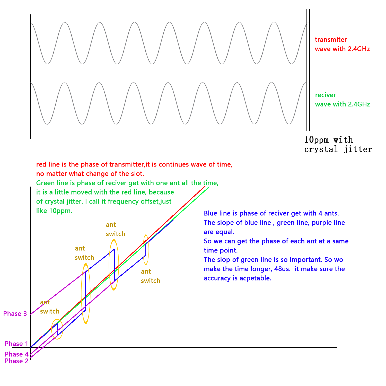
one sample every 125ns,one ant get 12us =96 samples.
and first 2+32 samples is ignored。
********************************************************************
// 1st ant 96 data of phase
0: -67 -55 -43 -31 -19 -7 6 18
8: 29 42 53 66 77 89 102 113
16: 125 137 149 161 173 186 198 -190
24: -179 -167 -156 -145 -134 -122 -111 -98
32: -86 -74 -61 -49 -36 -24 -12 2
40: 15 27 39 51 62 73 83 93
48: 103 114 124 134 145 157 169 180
56: 191 -198 -186 -174 -162 -149 -137 -124
64: -111 -99 -86 -74 -62 -50 -39 -28
72: -17 -5 8 20 31 42 54 66
80: 78 89 101 113 123 131 137 141
88: 143 141 78 -33 -35 -34 -28 -21
// 2nd ant 96 data of phase
96: -10 7 24 39 49 57 63 72
104: 82 95 110 124 137 150 162 173
112: 185 196 -194 -183 -171 -159 -148 -137
120: -127 -116 -104 -93 -81 -68 -57 -45
128: -34 -22 -10 4 15 27 39 51
136: 64 76 88 100 112 123 136 148
144: 160 172 184 195 -194 -183 -172 -160
152: -149 -137 -125 -111 -99 -87 -76 -65
160: -54 -43 -32 -20 -8 5 17 28
168: 40 52 65 77 89 100 112 124
176: 137 149 161 174 186 198 -192 -181
184: -171 -161 -150 -141 -131 -122 -113 -103
// 3rd ant 96 data of phase
192: -94 -84 -73 -61 -47 -35 -21 -8
200: 7 21 35 48 62 74 86 99
208: 111 122 134 147 158 171 181 193
216: -197 -187 -176 -165 -153 -140 -128 -117
224: -106 -94 -82 -71 -58 -46 -34 -23
232: -12 2 14 26 39 51 63 75
240: 88 100 112 124 136 148 159 172
248: 183 196 -193 -181 -169 -158 -147 -135
256: -124 -113 -101 -89 -77 -65 -54 -43
264: -32 -21 -11 2 14 25 38 51
272: 63 76 88 99 109 117 120 117
280: 109 97 84 75 71 71 76 86
// 4th ant 96 data of phase
288: 99 114 128 140 150 159 169 180
296: 192 -196 -183 -171 -159 -148 -136 -124
304: -112 -100 -87 -75 -62 -49 -36 -24
312: -13 -2 10 20 31 42 54 65
320: 78 90 102 114 125 137 148 161
328: 173 184 197 -193 -182 -170 -159 -147
336: -136 -125 -114 -102 -90 -78 -66 -54
344: -41 -28 -16 -4 10 21 34 46
352: 58 70 81 93 104 115 126 138
360: 150 162 174 186 198 -191 -181 -169
368: -158 -146 -133 -121 -108 -94 -78 -58
376: -35 -14 6 19 31 41 52 63
// 5th ant 96 data of phase
384: 76 89 103 116 126 136 146 155
392: 165 175 184 194 -196 -186 -175 -164
400: -153 -142 -130 -119 -108 -96 -85 -73
408: -61 -48 -35 -22 -9 4 16 28
416: 40 52 64 75 87 99 111 122
424: 134 146 158 170 181 193 -197 -185
432: -174 -163 -152 -140 -128 -117 -105 -92
440: -80 -68 -56 -44 -31 -19 -8 6
448: 18 30 42 54 67 78 90 103
456: 115 126 138 150 163 175 186 198
464: -190 -179 -166 -154 -141 -129 -117 -106
472: -94 -82 -71 -59 -48 -36 -25 -13
********************************************************************
void or_cfg()
{
NRF_RADIO->DFEMODE = RADIO_DFEMODE_DFEOPMODE_AoA;
NRF_RADIO->DFECTRL1 = 1<<RADIO_DFECTRL1_SAMPLETYPE_Pos| // 1:MagPhase 0:IQ
//--time 10*8 us
10 << RADIO_DFECTRL1_NUMBEROF8US_Pos |
//--crc behind
1 << RADIO_DFECTRL1_DFEINEXTENSION_Pos |
//--1:4us 2:2us 3:1us --> one sample len
2 << RADIO_DFECTRL1_TSWITCHSPACING_Pos |
1 << RADIO_DFECTRL1_TSAMPLESPACINGREF_Pos |
6 << RADIO_DFECTRL1_TSAMPLESPACING_Pos ;
//NRF_RADIO->DFECTRL2 = ((-32<<16)&0xfff0000)| //sample
// 0<<0; //switch
NRF_RADIO->CTEINLINECONF = 1 << RADIO_CTEINLINECONF_CTEERRORHANDLING_Pos |
0 << RADIO_CTEINLINECONF_CTEINFOINS1_Pos;
//DFE pin config
NRF_RADIO->PSEL.DFEGPIO[0] = ANTE;
NRF_RADIO->PSEL.DFEGPIO[1] = ANTS;
NRF_RADIO->PSEL.DFEGPIO[2] = ANTW;
NRF_RADIO->PSEL.DFEGPIO[3] = ANTN;
NRF_RADIO->SWITCHPATTERN = 1;//--for data recv
NRF_RADIO->SWITCHPATTERN = 1;//--for ref
NRF_RADIO->SWITCHPATTERN = 1;//--4us temp about 32 samples
NRF_RADIO->SWITCHPATTERN = 1;
NRF_RADIO->SWITCHPATTERN = 1;
NRF_RADIO->SWITCHPATTERN = 1;
NRF_RADIO->SWITCHPATTERN = 1;
NRF_RADIO->SWITCHPATTERN = 1;//5
NRF_RADIO->SWITCHPATTERN = 1;
NRF_RADIO->SWITCHPATTERN = 2;
NRF_RADIO->SWITCHPATTERN = 2;
NRF_RADIO->SWITCHPATTERN = 2;
NRF_RADIO->SWITCHPATTERN = 2;
NRF_RADIO->SWITCHPATTERN = 2;//5
NRF_RADIO->SWITCHPATTERN = 2;/**/
NRF_RADIO->SWITCHPATTERN = 4;
NRF_RADIO->SWITCHPATTERN = 4;
NRF_RADIO->SWITCHPATTERN = 4;
NRF_RADIO->SWITCHPATTERN = 4;
NRF_RADIO->SWITCHPATTERN = 4;//5
NRF_RADIO->SWITCHPATTERN = 4;
NRF_RADIO->SWITCHPATTERN = 8;
NRF_RADIO->SWITCHPATTERN = 8;
NRF_RADIO->SWITCHPATTERN = 8;
NRF_RADIO->SWITCHPATTERN = 8;
NRF_RADIO->SWITCHPATTERN = 8;//5
NRF_RADIO->SWITCHPATTERN = 8;
//-------------------------------------
NRF_RADIO->SWITCHPATTERN = 1;
NRF_RADIO->SWITCHPATTERN = 1;
NRF_RADIO->SWITCHPATTERN = 1;
NRF_RADIO->SWITCHPATTERN = 1;
NRF_RADIO->SWITCHPATTERN = 1;//5
NRF_RADIO->SWITCHPATTERN = 1;
NRF_RADIO->SWITCHPATTERN = 1;
NRF_RADIO->SWITCHPATTERN = 1;
NRF_RADIO->SWITCHPATTERN = 1;
NRF_RADIO->SWITCHPATTERN = 1;
NRF_RADIO->DFEPACKET.PTR = (u32)df_buf;
NRF_RADIO->DFEPACKET.MAXCNT = O_sizeof(df_buf);
}