This post is older than 2 years and might not be relevant anymore
More Info: Consider searching for newer posts

I need help with converting any example from Keil to SES

Hello,

I've been trying for days to convert any example from Keil to SES, I have road probably every question here on the dev zone but I am unable to fix this, I ever specially install windows on my mac to try if there it would work.

So, I have done everything from official nordic documents, I've been through several problems which I happily solve, but that I'm not able to.

I get those errors:


unplaced section: .log_dynamic_data_app [nrf_log_frontend.o], size=12, align=4

undefined symbol: __SRAM_segment_end__

undefined symbol: __start_log_const_data

undefined symbol: __start_log_dynamic_data

undefined symbol: __stop_log_const_data

I'm working on latest SEGGER, I have tried latest SDK, also 14.2 . The same errors. 

Thanks for reply

Parents Reply
  • Yes I am looking over right now and trying to understand:

    static const I2CCFG s_I2cCfg = {

    0, // I2C device number

    {

    {I2C0_SDA_PORT, I2C0_SDA_PIN, I2C0_SDA_PINOP, IOPINDIR_BI, IOPINRES_PULLUP, IOPINTYPE_OPENDRAIN},

    {I2C0_SCL_PORT, I2C0_SCL_PIN, I2C0_SCL_PINOP, IOPINDIR_OUTPUT, IOPINRES_PULLUP, IOPINTYPE_OPENDRAIN},

    },

    100000, // Rate

    I2CMODE_MASTER,

    5, // Retry

    0, // Number of slave addresses

    {0,}, // Slave addresses

    true, // DMA

    false, // Use interrupt

    7, // Interrupt prio

    NULL // Event callback

    };

    I2C g_I2c;


    #define TPH_I2C // To use I2C interface ---> If I change to TPH_SPI it would be using I2C yes?

    #ifdef TPH_I2C

    DeviceIntrf *g_pIntrf = &g_I2c;

    #else

    DeviceIntrf *g_pIntrf = &g_Spi;

    #endif

    That means defining I2C yes?

    SO I need to copy that and paste that to the motion_sensor_demo.cpp?
    And It should work? 


Children
  • Yes and don't forget the device address of the MPU in the config data.  in SPI the address is 0 (chip select idx 0 of the spi pin config). In I2C you need to set it to the I2C device address which is 0x68 or 0x69 depending on how you connect the ADD pin (See data sheet). 

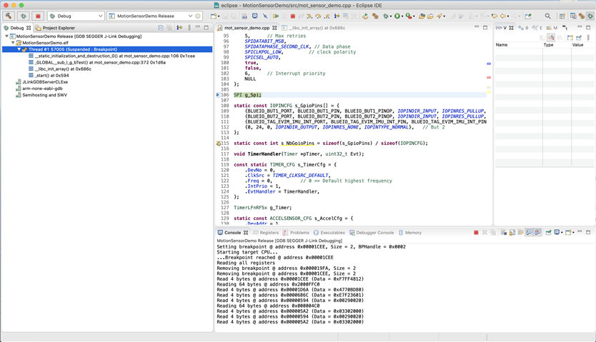
  • Hi, I have been studying the TPH DEMO and I2C_master_slave examples for 2 day now, and I did managed to build the code, but it's still not working. Actually it could be a problem that, I don't know where to find as you said "config data" ? In age_mpu9250.h the adress is defined as 0x68 so I think it should be okay but don't know if its enough. I attached you two screens of debug session and code of board.h and mot_sensor_demo.cpp please look at it and check whether something is wrong still?

    First thread:


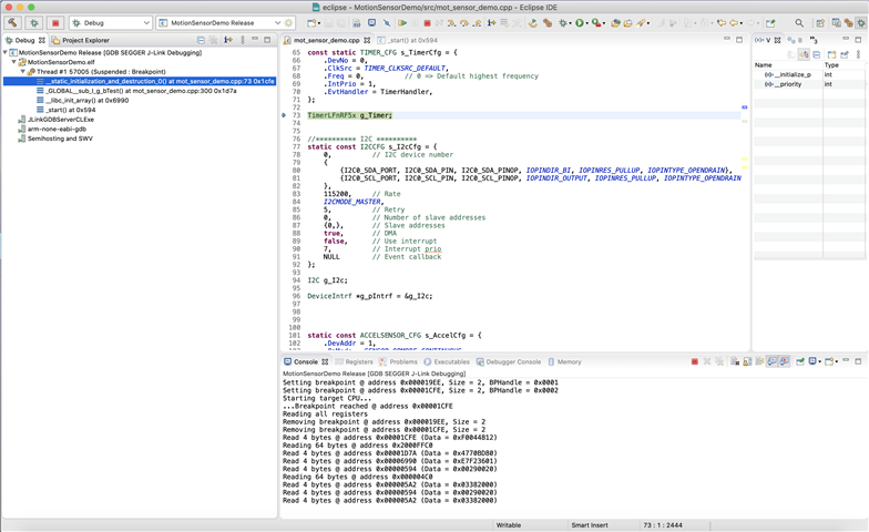
    After resume:


    And code for board.h

    #ifndef __BOARD_H__
    #define __BOARD_H__
    
    #include "nrf.h"
    #include "blueio_board.h"
    
    
    // For Nordic DevKit
    
    #define UART_TX_PIN					9
    #define UART_RX_PIN					11
    #define UART_RTS_PIN			    8
    #define UART_CTS_PIN				10
    
    #define SPI_DEVNO            		2
    #define SPI_MISO_PORT        		0
    #define SPI_MISO_PIN         		13
    #define SPI_MISO_PINOP       		1
    #define SPI_MOSI_PORT        		0
    #define SPI_MOSI_PIN         		12
    #define SPI_MOSI_PINOP       		1
    #define SPI_SCK_PORT         		0
    #define SPI_SCK_PIN          		11
    #define SPI_SCK_PINOP        		1
    
    #define SPI_BME280_CS_PORT         	0
    #define SPI_BME280_CS_PIN          	26
    #define SPI_BME280_CS_PINOP        	1
    
    //#define BLUEIO_TAG_BME680_PROTO
    #ifdef BLUEIO_TAG_BME680_PROTO
    #define I2C0_SDA_PORT					BLUEIO_TAG_BME280_I2C_SDA_PORT
    #define I2C0_SDA_PIN					BLUEIO_TAG_BME280_I2C_SDA_PIN
    #define I2C0_SDA_PINOP					BLUEIO_TAG_BME280_I2C_SDA_PINOP
    #define I2C0_SCL_PORT					BLUEIO_TAG_BME280_I2C_SCL_PORT
    #define I2C0_SCL_PIN					BLUEIO_TAG_BME280_I2C_SCL_PIN
    #define I2C0_SCL_PINOP					BLUEIO_TAG_BME280_I2C_SCL_PINOP
    #else
    #define I2C0_SDA_PORT					BLUEIO_TAG_BME680_I2C_SDA_PORT
    #define I2C0_SDA_PIN					BLUEIO_TAG_BME680_I2C_SDA_PIN
    #define I2C0_SDA_PINOP					BLUEIO_TAG_BME680_I2C_SDA_PINOP
    #define I2C0_SCL_PORT					BLUEIO_TAG_BME680_I2C_SCL_PORT
    #define I2C0_SCL_PIN					BLUEIO_TAG_BME680_I2C_SCL_PIN
    #define I2C0_SCL_PINOP					BLUEIO_TAG_BME680_I2C_SCL_PINOP
    #endif
    
    #endif // __BOARD_H__


    And mot_sensor_demo.cpp

    #include <stdio.h>
    #include <atomic>
    #include <inttypes.h>
    
    #include "nrf.h"
    #include "coredev/iopincfg.h"
    #include "coredev/i2c.h"
    #include "coredev/uart.h"
    #include "iopinctrl.h"
    #include "timer_nrf5x.h"
    #include "sensors/agm_mpu9250.h"
    #include "imu/imu_mpu9250.h"
    #include "stddev.h"
    #include "timer_nrf5x.h"
    #include "idelay.h"
    
    
    #define MPU9250
    #include "board.h"
    
    std::atomic<bool> g_bTest(false);
    
    //#include "sensor.h"
    //#define AK0991x_DEFAULT_I2C_ADDR	0x0C	/* The default I2C address for AK0991x Magnetometers */
    //#define AK0991x_SECONDARY_I2C_ADDR  0x0E    /* The secondary I2C address for AK0991x Magnetometers */
    
    void TimerHandler(Timer *pTimer, uint32_t Evt);
    
    const static TIMER_CFG s_TimerCfg = {
        .DevNo = 0,
    	.ClkSrc = TIMER_CLKSRC_DEFAULT,
    	.Freq = 0,			// 0 => Default highest frequency
    	.IntPrio = 1,
    	.EvtHandler = TimerHandler,
    };
    
    TimerLFnRF5x g_Timer;
    
    
    //********** I2C **********
    static const I2CCFG s_I2cCfg = {
    	0,			// I2C device number
    	{
    		{I2C0_SDA_PORT, I2C0_SDA_PIN, I2C0_SDA_PINOP, IOPINDIR_BI, IOPINRES_PULLUP, IOPINTYPE_OPENDRAIN},
    		{I2C0_SCL_PORT, I2C0_SCL_PIN, I2C0_SCL_PINOP, IOPINDIR_OUTPUT, IOPINRES_PULLUP, IOPINTYPE_OPENDRAIN},
    	},
    	115200,	    // Rate
    	I2CMODE_MASTER,
    	5,			// Retry
    	0,			// Number of slave addresses
    	{0,},		// Slave addresses
    	true,	    // DMA
    	false,		// Use interrupt
    	7,			// Interrupt prio
    	NULL		// Event callback
    };
    
    I2C g_I2c;
    
    DeviceIntrf *g_pIntrf = &g_I2c;


    static const ACCELSENSOR_CFG s_AccelCfg = {
    	.DevAddr = 1,
    	.OpMode = SENSOR_OPMODE_CONTINUOUS,
    	.Freq = 1000,
    	.Scale = 2,
    	.FltrFreq = 0,
    	.bInter = true,
    	.IntPol = DEVINTR_POL_LOW,
    };
    
    static const GYROSENSOR_CFG s_GyroCfg = {
    	.DevAddr = 0,
    	.OpMode = SENSOR_OPMODE_CONTINUOUS,
    	.Freq = 50000,
    	.Sensitivity = 10,
    	.FltrFreq = 200,
    };
    
    static const MAGSENSOR_CFG s_MagCfg = {
    	.DevAddr = 0,
    	.OpMode = SENSOR_OPMODE_CONTINUOUS,//SENSOR_OPMODE_SINGLE,
    	.Freq = 50000,
    	.Precision = MAGSENSOR_PRECISION_HIGH,
    };
    
    void ImuEvtHandler(Device * const pDev, DEV_EVT Evt);
    
    static const IMU_CFG s_ImuCfg = {
    	.EvtHandler = ImuEvtHandler
    };
    
    
    ImuMpu9250 g_Imu;
    AgmMpu9250 g_MotSensor;
    
    AccelSensor *g_pAccel = NULL;
    GyroSensor *g_pGyro = NULL;
    MagSensor *g_pMag = NULL;
    
    uint32_t g_DT = 0;
    static uint32_t g_TPrev = 0;
    
    void TimerHandler(Timer *pTimer, uint32_t Evt)
    {
        if (Evt & TIMER_EVT_TRIGGER(0))
        {
        }
    }
    
    void ImuEvtHandler(Device * const pDev, DEV_EVT Evt)
    {
    	ACCELSENSOR_DATA accdata;
    	IMU_QUAT quat;
    
    	switch (Evt)
    	{
    		case DEV_EVT_DATA_RDY:
    			g_MotSensor.Read(accdata);
    			g_Imu.Read(accdata);
    			printf("Accel %d: %d %d %d\r\n", accdata.Timestamp, accdata.X, accdata.Y, accdata.Z);
    			g_Imu.Read(quat);
    			printf("Quat %d: %d %d %d %d\r\n", quat.Timestamp, quat.Q1, quat.Q2, quat.Q2, quat.Q3);
    
    			break;
    	}
    }
    
    
    void ImuIntHandler(int IntNo)
    {
    	if (IntNo == 0)
    	{
    //		IOPinSet(0, 24);
    		uint32_t t = g_Timer.uSecond();
    		g_DT = t - g_TPrev;
    		g_TPrev = t;
    
    		//g_Imu.IntHandler();
    		//g_MotSensor.IntHandler();
    		//IOPinClear(0, 24);
    	}
    }
    
    
    bool HardwareInit()
    {
    	bool res;
    
    	g_Timer.Init(s_TimerCfg);
    
    	res = g_I2c.Init(s_I2cCfg);
    
    	if (res == true)
    	{
    		res = g_MotSensor.Init(s_AccelCfg, &g_I2c, &g_Timer);
    		if (res == true)
    		{
    			g_pAccel = &g_MotSensor;
    		}
    
    #if defined(MPU9250)
    		res = g_Imu.Init(s_ImuCfg, &g_MotSensor, &g_MotSensor, &g_MotSensor);
    #endif
    	}
    
    	if (res == true)
    	{
    		//IOPinCfg(s_GpioPins, s_NbGpioPins);
    		//IOPinEnableInterrupt(0, 6, BLUEIO_TAG_EVIM_IMU_INT_PORT, BLUEIO_TAG_EVIM_IMU_INT_PIN, IOPINSENSE_LOW_TRANSITION, ImuIntHandler);
    
    		int8_t m[9] = { 1, 0, 0,
    						0, 1, 0,
    						0, 0, 1 };
    
    		//g_Imu.SetAxisAlignmentMatrix(m);
    		//g_Imu.Quaternion(true, 6);
    	}
    
    	//uint64_t period = g_Timer.EnableTimerTrigger(0, 1UL, TIMER_TRIG_TYPE_CONTINUOUS);
    
    	//printf("period %u\r\n", (uint32_t)period);
    
    	return res;
    }
    //
    // Print a greeting message on standard output and exit.
    //
    // On embedded platforms this might require semi-hosting or similar.
    //
    // For example, for toolchains derived from GNU Tools for Embedded,
    // to enable semi-hosting, the following was added to the linker:
    //
    // --specs=rdimon.specs -Wl,--start-group -lgcc -lc -lm -lrdimon -Wl,--end-group
    //
    // Adjust it for other toolchains.
    //
    
    int main()
    {
    	bool res = HardwareInit();
    
    
    	if (res == false)
    	{
    		printf("Failed initializing hardware\r\n");
    
    		return 1;
    	}
    
    	printf("MotionSensorDemo\r\n");
    
    	ACCELSENSOR_RAWDATA arawdata;
    	ACCELSENSOR_DATA accdata;
    	GYROSENSOR_RAWDATA grawdata;
    	GYROSENSOR_DATA gyrodata;
    	MAGSENSOR_RAWDATA mrawdata;
    	IMU_QUAT quat;
    
    	memset(&arawdata, 0, sizeof(ACCELSENSOR_RAWDATA));
    	memset(&accdata, 0, sizeof(ACCELSENSOR_DATA));
    	memset(&gyrodata, 0, sizeof(GYROSENSOR_DATA));
    
    
    	uint32_t prevt = 0;
    	int cnt = 100;
    	while (1)
    	{
    		uint32_t t = g_Timer.uSecond();
    
    		//NRF_POWER->SYSTEMOFF = POWER_SYSTEMOFF_SYSTEMOFF_Enter;
    		//__WFE();
    		g_MotSensor.UpdateData();
    
    		uint32_t dt = arawdata.Timestamp - prevt;
    		prevt = arawdata.Timestamp;
    
    		g_MotSensor.Read(arawdata);
    
    		if (g_pGyro)
    		{
    			g_pGyro->Read(grawdata);
    		}
    
    		if (g_pMag)
    		{
    			g_pMag->Read(mrawdata);
    		}
    
    		g_Imu.Read(accdata);
    		//g_Imu.Read(quat);
    
    		if (cnt-- < 0)
    		{
    			cnt = 100;
    			printf("Accel %d %d: %d %d %d\r\n", (uint32_t)g_DT, (uint32_t)dt, arawdata.X, arawdata.Y, arawdata.Z);
    			//printf("Accel %d %d: %f %f %f\r\n", (uint32_t)g_DT, (uint32_t)dt, accdata.X, accdata.Y, accdata.Z);
    			//printf("Quat %d %d: %f %f %f %f\r\n", (uint32_t)g_DT, (uint32_t)dt, quat.Q1, quat.Q2, quat.Q3, quat.Q4);
    		}
    	}
    }


  • The config data is this.  All drivers from the library work the same way.  Populate its config structure and pass it to the init function.  

    // Config to use I2C
    static const ACCELSENSOR_CFG s_AccelCfg = {
    	.DevAddr = MPU9250_I2C_DEV_ADDR0,   // I2C device address
    	.OpMode = SENSOR_OPMODE_CONTINUOUS,
    	.Freq = 1000,
    	.Scale = 2,
    	.FltrFreq = 0,
    	.bInter = true,
    	.IntPol = DEVINTR_POL_LOW,
    };
    
    // Config to use SPI
    static const ACCELSENSOR_CFG s_AccelCfg = {
    	.DevAddr = 0,   // Index count of CS pin in the SPI pin map, first CS = 0, second CS = 1,... 
    	.OpMode = SENSOR_OPMODE_CONTINUOUS,
    	.Freq = 1000,
    	.Scale = 2,
    	.FltrFreq = 0,
    	.bInter = true,
    	.IntPol = DEVINTR_POL_LOW,
    };

    example config for I2C

    static const I2CCFG s_I2cCfg = {
    	0,			// I2C device number
    	{
    		{I2C0_SDA_PORT, I2C0_SDA_PIN, I2C0_SDA_PINOP, IOPINDIR_BI, IOPINRES_PULLUP, IOPINTYPE_OPENDRAIN},
    		{I2C0_SCL_PORT, I2C0_SCL_PIN, I2C0_SCL_PINOP, IOPINDIR_OUTPUT, IOPINRES_PULLUP, IOPINTYPE_OPENDRAIN},
    	},
    	115200,	    // Rate
    	I2CMODE_MASTER,
    	5,			// Retry
    	0,			// Number of slave addresses
    	{0,},		// Slave addresses
    	true,	    // DMA
    	false,		// Use interrupt
    	7,			// Interrupt prio
    	NULL		// Event callback
    };
    

  • Okay I corrected it, thanks, now I now what've meant. But debug did not change. Failed initializing hardware. 

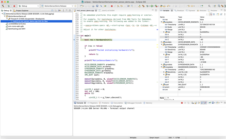
    I attached photos in earlier comment, can you have a look and tell me what else could be making this error?

    First is en error with TimerLFnRF5x g_Timer; and I really have no clue what is wrong? 

    and the second is with 

    bool res = HardwareInit(); so I assume that It still did not see the mpu9250?

  • There are no error. Everything is working.  The Timer is just a timer instance.  The Segger just break at instantiation of that object, nothing special.  Just continue execution.

Related