This post is older than 2 years and might not be relevant anymore
More Info: Consider searching for newer posts

NRF53 High power consumption on in power_off state - Zephyr

Hi

I've run up the system_off sample (samples/boards/nrf/system_off) and I can see chip fall into deep sleep, but deep sleep still seems to be sitting at 152 microamps, which seems to be quite high?

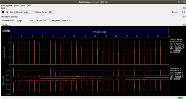
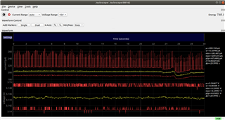
Below are the usage screenshots, first one showing dropping from active to power_off state, and the second showing the consumption over 30 seconds in power_off state

Drop to power_off state

power off state

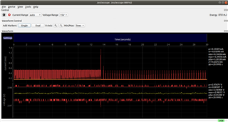
I have tried turning off UART, as this could be a possible cause of consumption in power_off state. I know that it is not waking up out of power_off state because I can see that in the consumption, but it is still using power.

Why is it still using this much power?

Parents
  • Hi, are you measuring on a DK? Which version is it? I know that at least 0.7.0 has some current consumption problems.

  • Hi yes I am measuring the current on the nrf53 DK but I have also measured it on a few custom boards and it is high consumption still. Not sure which version you're referring to?

  • Hi Christian

    The most common way to measure current is to cut solder bridge SB9, and connect an ammeter to the P22 - nRF current measurement connector. Then you can directly measure the current going into the chip (excluding external current consumption from LED's and other DK electronics). 

    When doing this it is important to short P22 whenever you don't use the ammeter, otherwise current to the chip will be cut (or reconnect SB9). 

    Alternatively it should be possible to supply the chip through the P21 - External supply connector, and measure the current going to the board if you have a tool that can supply the chip while measuring the current. 

    The board I have been testing on is v1.2.1 (2017.22), so a slightly older one, but I doubt the board version is the issue. To my knowledge the difference between these two versions are minimal. 

    Best regards
    Torbjørn

  • Thanks for your help! I do have a tool that can supply the chip while measuring the current so i'll go with that option, I'm a little confused with your instructions though - 
    1) I thought P21 was the reset pin for the nRF52? Confused as to how to use that for supplying voltage here
    2) I have been supplying voltage through the external supply pins - is that not the same as the external supply connector? Because i thought the complication there was that it was also measuring the other components on the board and not only the chip consumption?

    Sorry for not understanding

  • Hi Christian

    1) All the headers and connectors on the board have a unique Pxx name. If you look closely at the PCB you should see this printed in white next to the connector. 

    The GPIO names should start with the port number followed by the pin number, so P0.21, not just P21. 

    2) I assume it is the same, yes. If you can see "P21" printed next to them then we are on the same page Slight smile

    Best regards
    Torbjørn

  • Thanks for clearing that up Torbjørn - I have indeed been supplying voltage through P21 and measuring the current there. Does that not also measure the consumption of the other components on the board, or does it only measure consumption from the chip? Because that's where I'm finding high consumption readings. 
    I'm also not sure why my consumption readings are different to yours... I have tested on two different NRF52 PCA10040 boards to confirm it's not just a faulty board. Perhaps you can supply the hex file you are flashing to the board and i'll try running the exact same as you and measuring what I get?

    Could you also confirm that the following would be the process?
    1) Flash the hex over USB
    2) Unplug USB, provide 3v over P21
    3) Measure consumption over P21

    Thanks again for your help!

  • Hi Christian

    On the nRF52840DK you can set the SW10 switch to ON, and set SW6 to "nRF Only". Then you will bypass the Segger chip and other electronics and only power the nRF device, which should ensure correct current measurement results. 

    On the nRF52DK this is not possible, and it is recommended to measure the current consumption through P22 to get accurate results. 

    Christian Holland said:
    Could you also confirm that the following would be the process?
    1) Flash the hex over USB
    2) Unplug USB, provide 3v over P21
    3) Measure consumption over P21

    Yes, on the nRF52840DK this should work fine if you follow my instructions above, but apparently this is not a good method on the nRF52DK. 

    Below you will find the hex file I used on the nRF52DK, which blinks the LED's and draws around 16uA, but this is using the ammeter on P22 method. 

    zephyr_blinky_no_serial.hex

    If you need to measure the current flowing into P21 on the nRF52DK this is also possible, but significantly more complicated. 

    My colleague Stian describes the procedure here:
    https://devzone.nordicsemi.com/f/nordic-q-a/20023/how-to-power-the-nrf52-chip-as-standalone-without-the-dk

    Best regards
    Torbjørn

Reply
  • Hi Christian

    On the nRF52840DK you can set the SW10 switch to ON, and set SW6 to "nRF Only". Then you will bypass the Segger chip and other electronics and only power the nRF device, which should ensure correct current measurement results. 

    On the nRF52DK this is not possible, and it is recommended to measure the current consumption through P22 to get accurate results. 

    Christian Holland said:
    Could you also confirm that the following would be the process?
    1) Flash the hex over USB
    2) Unplug USB, provide 3v over P21
    3) Measure consumption over P21

    Yes, on the nRF52840DK this should work fine if you follow my instructions above, but apparently this is not a good method on the nRF52DK. 

    Below you will find the hex file I used on the nRF52DK, which blinks the LED's and draws around 16uA, but this is using the ammeter on P22 method. 

    zephyr_blinky_no_serial.hex

    If you need to measure the current flowing into P21 on the nRF52DK this is also possible, but significantly more complicated. 

    My colleague Stian describes the procedure here:
    https://devzone.nordicsemi.com/f/nordic-q-a/20023/how-to-power-the-nrf52-chip-as-standalone-without-the-dk

    Best regards
    Torbjørn

Children
Related