Hello nordic, I have used the nrf24 before with ARM, and this go around its AVR, not that that changes much but looking for some help. I'm familiar with how this chip work and the data sheet as well as the tutorials. I only have one arduino atm so I can not test that the modals are working but have little reason to think they are bad. As for the SPI side of things I'm good there... I'm just not seeing my replies on the arduino end, so my set up must be busted.
Issues.
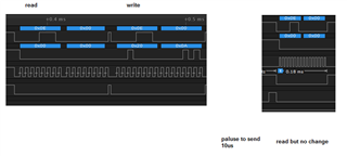
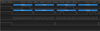
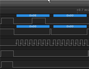
1) I can not find the reply section in the data sheet, I just do not remember where it is. I get the 0x0e, 0x00 with most all address rights except 0x20, that one gives me an 0xe7 on the first byte.
send 0x20 (reply 0x0e) send 0x0a (reply:0xe7)
where can I look up the e7?
2) A future question if I may, in theory, I could send a code and receive data right? That is to say my transmit can send 0x44 (maybe more bytes) and expect a reply from the receiver? Or is this going to be a single direction communication? If it is single direction, I assume I can always swap the roles? I never used it that way before.
3) my code, I'm pretty sure the CE CSN stuff is correct based on the replies on the spi. This is for the transmit end.
void pulse (void)//my CE pulse
{
ATT_ON();_delay_us(10);ATT_OFF();
}
void Enable(void) //these are my CSN states
{
PORTB &= ~0x01;
_delay_us(1);
}
void Disable(void)
{
PORTB |= 0x01;
_delay_us(1);
}
/////////////////my init////////////////////
Enable();
sendCommand(0x20);sendCommand(0x0A);//Config : 00001010 enalbe crc, crc 1 byte, power up, ptx
Disable();
//disable auto retrans
Enable();
sendCommand(0x24);sendCommand(0);
Disable();
//rxaddress
Enable();
sendCommand(0x22);sendCommand(0x03);//rxaddress, I think this should be 1 but ardino says 3
Disable();
//set channel to 5.
Enable();
sendCommand(0x25);sendCommand(5);//PF channel : 5
Disable();
//data rate of 2mb
Enable();
sendCommand(0x26);sendCommand(0x09);// RF set up : matching what I see in ardino 18db and rate of 2mb
Disable();
//addres for 5 bytes
Enable();
sendCommand(0x23);sendCommand(3);//11 means 5 byte address
Disable();
const char *addr = "AIR05";
Enable();//tx address
//sendCommand(0x30);sendCommand(addr[0]);sendCommand(addr[1]);sendCommand(addr[2]);sendCommand(addr[3]);sendCommand(addr[4]);//set tx pipe address.
sendCommand(0x30);sendCommand(addr[0]);sendCommand(addr[1]);sendCommand(addr[2]);sendCommand(addr[3]);sendCommand(addr[4]);//set tx pipe address.
Disable();
Enable();
sendCommand(0x00);sendCommand(0);//read Config
Disable();
////////////////end init/////////////
////////////////send//////////// - this will loop
Enable();
sendCommand(0x31);sendCommand(size);// size for data
Disable();
Enable();
sendCommand(0xa0);sendCommand(data); //0xb0 for no ack
//other bytes here.
Disable();
pulse();
/////////////send end/////////
on my arduino ill just post the config set up reply.
before my config
STATUS = 0x0e RX_DR=0 TX_DS=0 MAX_RT=0 RX_P_NO=7 TX_FULL=0
RX_ADDR_P0-1 = 0x3030303030 0xc2c2c2c2c2
RX_ADDR_P2-5 = 0xc3 0xc4 0xc5 0xc6
TX_ADDR = 0xe7e7e7e7e7
RX_PW_P0-6 = 0x20 0x00 0x00 0x00 0x00 0x00
EN_AA = 0x3f
EN_RXADDR = 0x03
RF_CH = 0x4c
RF_SETUP = 0x01
CONFIG = 0x0e
DYNPD/FEATURE = 0x00 0x00
Data Rate = 1MBPS
Model = nRF24L01+
CRC Length = 16 bits
PA Power = PA_MIN
after
STATUS = 0x0e RX_DR=0 TX_DS=0 MAX_RT=0 RX_P_NO=7 TX_FULL=0
RX_ADDR_P0-1 = 0x3030303030 0xc2c2c2c2c2
RX_ADDR_P2-5 = 0xc3 0xc4 0xc5 0xc6
TX_ADDR = 0xe7e7e7e7e7
RX_PW_P0-6 = 0x20 0x00 0x00 0x00 0x00 0x00
EN_AA = 0x3f
EN_RXADDR = 0x03
RF_CH = 0x05
RF_SETUP = 0x09
CONFIG = 0x0b
DYNPD/FEATURE = 0x00 0x00
Data Rate = 2MBPS
Model = nRF24L01+
CRC Length = 8 bits
PA Power = PA_MIN