My current project is to build a simple BLE LED controller. The goals of this project are to familiarize myself with lower level modules and to practice designing/building circuits. That is why I am not using the evaluation board and am instead trying to build my own. As a warning/preemptive apology, most of my BLE experience is with BeagleBones and Arduinos, and I am generally a novice with electrical engineering.
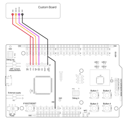
My plan was to use Fanstel's BM833 module, which is built around the nRF52833 chip. I would design/print a simple breakout board for the pins that I need from the chip. The bulk of the project would be designing and printing a custom development board that I would use to program the chip from my Mac. I plan on using the FT232RL USB to serial breakout board and adding an EC3-.327 32kHz crystal oscillator.
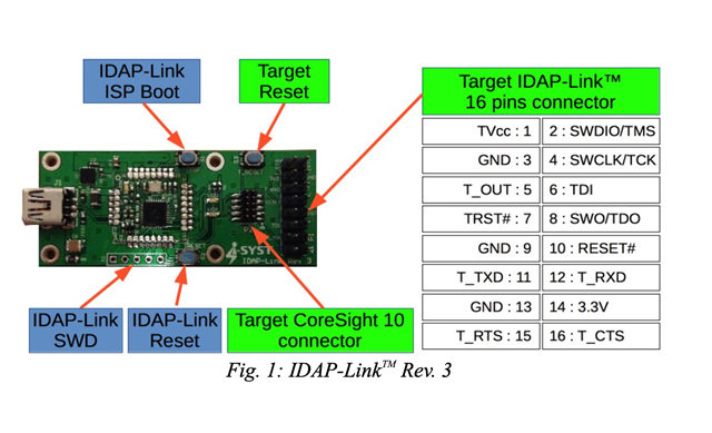
I am currently stuck on figuring out how to prepare and upload a program to the chip from Segger. I have been following this tutorial (among many others), but that one assumes I have the development kit. Could you offer any guidance on how to design my own device? Would I need a J-Link programmer like this one no matter what? How would I use that?
I am also still a little confused about the difference between a bootloader, a SoftDevice, and an application. This thread says:
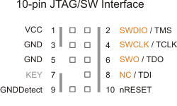
When you want to send data over BLE or ANT, you first flash BLE softdevice or ANT softdevice and then put you application on top of that. With that you can send data over BLE or ANT. You do not need any bootloader to do this. You need to program the device by connecting a programmer to the SWD programming interface on the nRF51.
So do I not even need a bootloader? Do I need to first flash the SoftDevice (I was thinking S113) and then upload the application? The tutorial I linked to above shows how to upload/run using Segger and a development kit, but the goal of my project is to use Segger with my own device and avoid the dev kit.
Any and all advice would be greatly appreciated!! I'm having trouble getting a bird's eye view of the project, and it's getting a bit maddening...