
Hi!
I'm trying to measure the voltage drop across a custom PCB we're developing. This was done while trying to get a clear sense of the current consumption used by our board, using a PPK on top of a DK, with a setup similar to the one described in figure 2 here.
What we find is that we measure a ~2.1V drop across our PCB, while connecting a DMM in parallel to the PCB, not the 'expected' 3V from the battery.
Reading a post here on dev zone, which referenced this article on the affects connecting a voltmeter has on the measured circuit, I believe our measurements are sound, but I wanted to run this by smarter people.
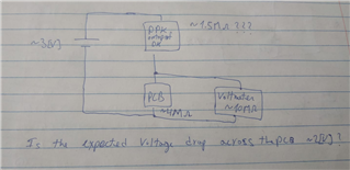
So, using the resistance measurement option in our DMM, we measured ~4M Ohm on our PCB between VDD and GND, and ~1.5M Ohm between the two pins of the external DUT connector (P16) on the PPK, to get the equivalent resistance of the DK+PPK. I'm not sure how accurate this method is. We are also assuming a ~10MOhm resistance to our voltmeter.
Using the above figures, and assuming the PPK+DK equivalent load is sequential to our parallel voltmeter+PCB load, we get an expected voltage drop of about ~2V across our PCB.
My questions are:
1. Is an equivalent resistance of ~1.5M Ohm to the PPK + DK sound reasonable?
2. Is our assumption that the PPK is in sequence with the PCB correct for the described connection?
3. Is the 2V reading on our PCB nothing to be concerned about, as we suspect?
Thanks!

