
Hi,
I have a project based on the NUS (Nordic Uart Service) example.
I have bought a USB dongle MDBT50Q-RX manufactured by RAYTAC (https://www.raytac.com/product/ins.php?index_id=89), but I am not sure how to deploy my application to it. I would like to see if there is anyone here have experience on USB dongle which could give me some suggestion or guide.
At first, I just insert the USB dongle to the PC's USB. The PC can recognize the USB (Image 1) but nrf Connect for Desktop application (latest version, i.e. nRF Connect v3.3.1, Programmer v1.4.1) said the device does not support (Image 2), tested on both Mac OS and Windows.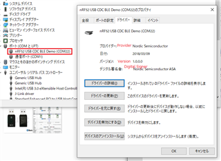
(Image 1)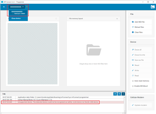
(Image 2)
Afterward I found these blog pages:
raytaccorp.blogspot.com/.../burn-your-firmware-onto-mdbt50q-rx-that.html
raytaccorp.blogspot.com/.../firmware-coding-dfu-onto-mdbt50q-rx.html
So I tried to wired with J-Link, I am able to burn my firmware either through SEGGER Embedded Studio > Target > Download ble_app_uart_c_pca10056_s140 or nrf Connect for Desktop. Just like other devices I previously used.
(Image 3, Sample of the dongle connected with J-Link RTT Viewer can view the NRF_LOG properly)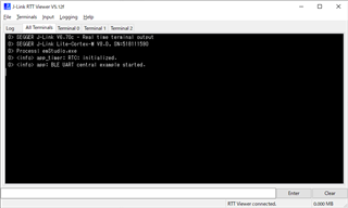
(Image 3)
However after burned and insert the dongle to PC, the COM port does not appear (Image 4).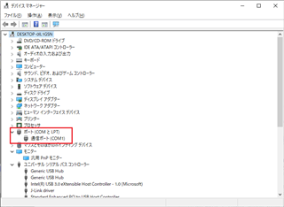
(Image 4)
Am I missing something like incorrect setting?
Thank you very much.
Joe

