This post is older than 2 years and might not be relevant anymore
More Info: Consider searching for newer posts

nRF52832 PCB Antenna questions about addition of microwave jumper and "C15" 1.2 pF capacitor

I am working on my first nRF52832 design utilizing a 4 layer PCB.  I have been reviewing the different antenna options for this device and have some questions about the PCB antenna solution.  First, there are quite a few differences between the older development board (version 0.9) and the new recommended layout.  Notably, the dev board has a microwave jumper on it (presumably for hooking up a network analyzer?).  The latest reference design does not include this component but instead only shows the transmission line up to a 30x30 mil pad.  The guidelines say that all components/pcb features must match to get optimal results.  How does the addition of the jumper affect the impedance of the line? (note that I am no RF expert by any means).  does the jumper connect by another length of trace to the 30x30 pad or can the jumper pad replace this?  Also, for the PCB antenna, the guidelines show a "C15" 1.2 pF capacitor shunting the ANT net.  If I use the microwave jumper, which side of the jumper should this capacitor be on?   Thanks Rich

Parents
  • Thanks Andreas, that helps.

    The next question i am trying to get my "DC brain" around is how the impedance's of the transmission line (designed to be 50 ohms) and the microwave jumper interact.  From what you are saying, it would be incorrect to say that Z0 = Ztl + Zuwj where Z0 is the characteristic "total" impedance, Ztl is the "Transmission line impedance", and Zuwj is the impedance of the microwave jumper?  Instead I am getting the gist that putting these 50 ohm elements "in series" is what is desired?  Can you provide any sources on this subject?

    Thanks again

    Rich

Reply
  • Thanks Andreas, that helps.

    The next question i am trying to get my "DC brain" around is how the impedance's of the transmission line (designed to be 50 ohms) and the microwave jumper interact.  From what you are saying, it would be incorrect to say that Z0 = Ztl + Zuwj where Z0 is the characteristic "total" impedance, Ztl is the "Transmission line impedance", and Zuwj is the impedance of the microwave jumper?  Instead I am getting the gist that putting these 50 ohm elements "in series" is what is desired?  Can you provide any sources on this subject?

    Thanks again

    Rich

Children
  • Hi Rich,


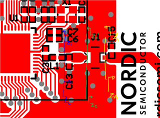
    The characteristic impedance of the transmission line indicates which load impedance it is matched to. It might be easier to illustrate (warning: high-level paint art)

    Z_A above is 50 ohm and presents a load impedance to whatever is connected to it, in this case a coaxial connector, transmission line and, to the left of the blue line, the nRF52 radio. Now by choosing a transmission line with 50 ohm impedance (let's treat the coaxial connector as a transmission line), then Z_C (another load impedance, everything to the right of the green line) will be equal to Z_A. If not 50 ohm, Z_C will become mismatched from Z_A, and there will be an insertion loss from a 50 ohm source into Z_C.

    This maps similarly as we move further toward the left along the coplanar waveguide, to the blue line. If the coaxial connector and coplanar waveguide have (in sum) 50 ohm characteristic impedance then Z_L = Z_A. Z_L will be matched to Z_A, meaning there will be minimal insertion loss. You want this because the nRF52832 radio is designed for a 50 ohm load, which Z_L then presents the radio with.

    This should be the essentials, main takeaways is to use a 50 ohm transmission line, either calculate it and dimension it manually or use CAD built-in calculators/tools or impedance control in production. If ever in doubt we are here to help either you want to ask a question like in this ticket, or if you want us to review your designs and make sure the RF part is good.


    So yes in one way putting the 50 ohm components in series sort of make the impedance in the end 50ohm, but it is not really summed together.


    Best regards,

    Andreas

Related