
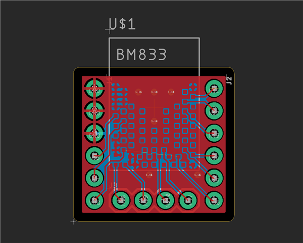
I am making a simple breakout board for the nRF52833 (I'm using Fanstel's BM833 module). This is what my board is looking like. There's a ground plain on the top and the bottom:
I am almost 100% sure that I need to connect all the grounds, and the plane does a good job of that (with vias interspersed throughout the board to connect the two planes). Two questions I still have are:
1. I assume VBUS remains separate, but do I need to connect the VDDs to each other? According to this other thread, the NRF52833 does not support powering external devices from VDD, so why have more than one in the first place?
2. Do I need any decoupling capacitors? If so, where should they go?
Also, as I understand it, these capacitors are like buffers to prevent spikes/buildups in charge. Is that right?
