Hello,
I am trying to get the I2S peripheral working for the first time. The problem could be something very silly. I am using a BMD-350 which is a NRF52832 inside a module and lots of other peripherals are working just fine on a custom board. I am attempting to interface the NRF52 with a SPH0645 which is an I2S mono microphone. It's a 24bit device, needs 32 clocks. I am using 2 PWM outputs to output a roughly 3Mhz signal for the BCLK and a BCLK/64 for the WS signal. Microphone is set to only output with SEL grounded. I am looking at the signals on an oscope and I see a BCLK, a WS, and the data out from the microphone in perfect I2S. Everything on the wire looks excellent. I have also verified solder connection by sending my PWM signal out the SDIN line temporarily and it wiggles. Therefore, the physical path into the NRF52 seems to be working.
What doesn't seem to be working is getting any data read back. The handler interrupt gets called once at the very beginning, and it never gets called again. Both of the 2 buffers are completely empty, all zeros. The interrupt never fires again. I see data moving on the scope.
Not really sure what's wrong as so much of the libraries are buried away to just make magic happen. When it doesn't happen, I have no idea where to look to debug.
I do notice that if I change the pins in the sdk_config.h file to the actual values, the i2s start functions just fail. It fails on the part where it is trying to purpose the pin. At this point I have no idea WTF all these handlers and mappings are for. They seem redundant yet, overwrite eachother. In the sdk_config there is a I2S_ENABLED section with all sorts of config, then a NRFX_I2S_ENABLED section with the exact same config, and then in my c code there is another instance of config. If I set the pin for SCK under the I2S_ENABLED section of sdk_config, the code fails to even start up. Same with the other sections. If I actually set all the areas to have the same correct data like the right pins, nothing works. I would hope that the C code is what actually makes the I2S port do it's thing. But there is obviously something at play with that god awful h file.
My data handler thing is essentially the example, but with the tx buffer being NULL.
static void data_handler(nrfx_i2s_buffers_t const *p_released, uint32_t status)
{
    /*
    // Non-NULL value in 'p_data_received' indicates that a new portion of
    // data has been received and should be processed.
    if (p_released->p_rx_buffer != NULL)
    {
        check_rx_data(p_released->p_rx_buffer, I2S_BUFFER_SIZE);
    }
    */

     // 'nrf_drv_i2s_next_buffers_set' is called directly from the handler
    // each time next buffers are requested, so data corruption is not
    // expected.
    ASSERT(p_released);

    // When the handler is called after the transfer has been stopped
    // (no next buffers are needed, only the used buffers are to be
    // released), there is nothing to do.
    if (!(status & NRFX_I2S_STATUS_NEXT_BUFFERS_NEEDED))
    {
        return;
    }

    // First call of this handler occurs right after the transfer is started.
    // No data has been transferred yet at this point, so there is nothing to
    // check. Only the buffers for the next part of the transfer should be
    // provided.
    if (!p_released->p_rx_buffer)
    {
        nrf_drv_i2s_buffers_t const next_buffers = {
            .p_rx_buffer = m_buffer_rx[1],
            // .p_tx_buffer = m_buffer_tx[1],
        };
        APP_ERROR_CHECK(nrf_drv_i2s_next_buffers_set(&next_buffers));

        // mp_block_to_fill = m_buffer_tx[1];
    }
    else
    {
        // mp_block_to_check = p_released->p_rx_buffer;
        check_rx_data(p_released->p_rx_buffer, I2S_BUFFER_SIZE);


        // The driver has just finished accessing the buffers pointed by
        // 'p_released'. They can be used for the next part of the transfer
        // that will be scheduled now.
        APP_ERROR_CHECK(nrf_drv_i2s_next_buffers_set(p_released));

        /*
        // The pointer needs to be typecasted here, so that it is possible to
        // modify the content it is pointing to (it is marked in the structure
        // as pointing to constant data because the driver is not supposed to
        // modify the provided data).
        mp_block_to_fill = (uint32_t *)p_released->p_tx_buffer;
        */
    }
}
The buffer:
static uint32_t          m_buffer_rx[2][I2S_BUFFER_SIZE];
static uint32_t          lsample_buffer_rx[(I2S_BUFFER_SIZE/2)];
Init the I2S mic and PWMs with lots of debug stuff in there too... (Note that the PWM frequency was changed to be 2x slower for debug incase it was timing related)
bool sph0645_init(void)
{
    uint32_t err_code = NRF_SUCCESS;

    memset(sph0645_steth_FIFO, 0, sizeof(sph0645_steth_FIFO)); // Clear the FIFO Buffer

     nrf_gpio_cfg(
        STETH_MM_BCLK_WORKAROUND_PWM_I2S_PIN,
        NRF_GPIO_PIN_DIR_OUTPUT,
        NRF_GPIO_PIN_INPUT_DISCONNECT,
        NRF_GPIO_PIN_NOPULL,
        NRF_GPIO_PIN_H0H1,
        NRF_GPIO_PIN_NOSENSE);
     nrf_gpio_cfg(
        STETH_MM_WS_I2S_PIN,
        NRF_GPIO_PIN_DIR_OUTPUT,
        NRF_GPIO_PIN_INPUT_DISCONNECT,
        NRF_GPIO_PIN_NOPULL,
        NRF_GPIO_PIN_H0H1,
        NRF_GPIO_PIN_NOSENSE);
     nrf_gpio_cfg(
        STETH_MM_BCLK_I2S_PIN,
        NRF_GPIO_PIN_DIR_INPUT,
        NRF_GPIO_PIN_INPUT_DISCONNECT,
        NRF_GPIO_PIN_NOPULL,
        NRF_GPIO_PIN_H0H1,
        NRF_GPIO_PIN_NOSENSE);
     nrf_gpio_cfg(
        STETH_MM_SDIN_WORKAROUND_I2S_PIN,
        NRF_GPIO_PIN_DIR_INPUT,
        NRF_GPIO_PIN_INPUT_DISCONNECT,
        NRF_GPIO_PIN_NOPULL,
        NRF_GPIO_PIN_H0H1,
        NRF_GPIO_PIN_NOSENSE);
     nrf_gpio_cfg(
        STETH_MM_DATAIN_I2S_SDIN_PIN,
        NRF_GPIO_PIN_DIR_INPUT,
        NRF_GPIO_PIN_INPUT_DISCONNECT,
        NRF_GPIO_PIN_NOPULL,
        NRF_GPIO_PIN_H0H1,
        NRF_GPIO_PIN_NOSENSE);
     nrf_gpio_cfg(
        STETH_MM_DATAOUT_I2S_SDOUT_PIN,
        NRF_GPIO_PIN_DIR_INPUT,
        NRF_GPIO_PIN_INPUT_DISCONNECT,
        NRF_GPIO_PIN_NOPULL,
        NRF_GPIO_PIN_H0H1,
        NRF_GPIO_PIN_NOSENSE);


    // Define the I2S configuration; running in slave mode and using PWM outputs to provide synthetic SCK and LRCK
    nrfx_i2s_config_t config = NRF_DRV_I2S_DEFAULT_CONFIG;
        config.sdin_pin             = STETH_MM_SDIN_WORKAROUND_I2S_PIN;
        config.sdout_pin            = STETH_MM_DATAOUT_I2S_SDOUT_PIN;
        config.mode                 = NRF_I2S_MODE_SLAVE;
        config.mck_setup            = NRF_I2S_MCK_DISABLED;
        config.sample_width         = NRF_I2S_SWIDTH_24BIT;
        config.channels             = NRF_I2S_CHANNELS_LEFT;                                                    // Set the I2S microphone to output on the left channel, SEL is hardwired low on board
        config.format               = NRF_I2S_FORMAT_ALIGNED;
        config.alignment            = NRF_I2S_ALIGN_LEFT;
    err_code                    = nrfx_i2s_init (&config, data_handler);                                  // Initialize the I2S driver
    APP_ERROR_CHECK(err_code);

    // 1-channel PWM; 16MHz clock and period set in ticks.
    // The user is responsible for selecting the periods to guve the correct ratio for the I2S frame length
    app_pwm_config_t pwm1_cfg = APP_PWM_DEFAULT_CONFIG_1CH(10L, STETH_MM_BCLK_WORKAROUND_PWM_I2S_PIN);                           // SCK; pick a convenient gpio pin
    app_pwm_config_t pwm2_cfg = APP_PWM_DEFAULT_CONFIG_1CH(640L, STETH_MM_WS_I2S_PIN);                                          // LRCK; pick a convenient gpio pin. LRCK period = 64X SCK period


    // Initialize and enable PWM's
    err_code = app_pwm_ticks_init(&PWM1,&pwm1_cfg,pwm_ready_callback);
    APP_ERROR_CHECK(err_code);
    err_code = app_pwm_ticks_init(&PWM2,&pwm2_cfg,pwm_ready_callback);
    APP_ERROR_CHECK(err_code);


     nrf_gpio_cfg(
        STETH_MM_BCLK_WORKAROUND_PWM_I2S_PIN,
        NRF_GPIO_PIN_DIR_OUTPUT,
        NRF_GPIO_PIN_INPUT_DISCONNECT,
        NRF_GPIO_PIN_NOPULL,
        NRF_GPIO_PIN_H0H1,
        NRF_GPIO_PIN_NOSENSE);
     nrf_gpio_cfg(
        STETH_MM_WS_I2S_PIN,
        NRF_GPIO_PIN_DIR_OUTPUT,
        NRF_GPIO_PIN_INPUT_DISCONNECT,
        NRF_GPIO_PIN_NOPULL,
        NRF_GPIO_PIN_H0H1,
        NRF_GPIO_PIN_NOSENSE);
     nrf_gpio_cfg(
        STETH_MM_BCLK_I2S_PIN,
        NRF_GPIO_PIN_DIR_INPUT,
        NRF_GPIO_PIN_INPUT_DISCONNECT,
        NRF_GPIO_PIN_NOPULL,
        NRF_GPIO_PIN_H0H1,
        NRF_GPIO_PIN_NOSENSE);
     nrf_gpio_cfg(
        STETH_MM_SDIN_WORKAROUND_I2S_PIN,
        NRF_GPIO_PIN_DIR_INPUT,
        NRF_GPIO_PIN_INPUT_DISCONNECT,
        NRF_GPIO_PIN_NOPULL,
        NRF_GPIO_PIN_H0H1,
        NRF_GPIO_PIN_NOSENSE);

    app_pwm_enable(&PWM1);
    app_pwm_enable(&PWM2);
    app_pwm_channel_duty_set(&PWM1, 0, 50);                                                                // Set at 50% duty cycle for square wave
    app_pwm_channel_duty_set(&PWM2, 0, 50);


    // return true;

    // Instantiate I2S
    /*
    nrfx_i2s_buffers_t i2s_buffers;
    i2s_buffers.p_rx_buffer = &m_buffer_rx;
    i2s_buffers.p_tx_buffer = NULL;
    err_code = nrf_drv_i2s_start(&i2s_buffers, I2S_BUFFER_SIZE, 0);
    */

    nrf_drv_i2s_buffers_t const i2s_buffers = {
        NULL,
        .p_rx_buffer = m_buffer_rx[0],
    };
    err_code = nrf_drv_i2s_start(&i2s_buffers, I2S_BUFFER_SIZE, 0);


    APP_ERROR_CHECK(err_code);
    memset(m_buffer_rx, 0xCC, sizeof(m_buffer_rx));                                                        // Initialize I2S data callback buffer

    return true;
}
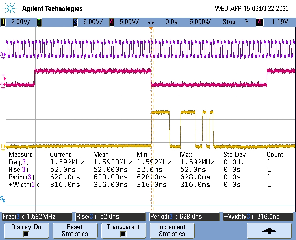
Channel 3 (top) - BCLK out from NRF52 into SPH
Channel 4 (middle) - WS out from NRF52 into SPH
Channel 1 (bottom) - DATA out from SPH into NRF52