This post is older than 2 years and might not be relevant anymore
More Info: Consider searching for newer posts

Custom board NRF52832 blinking LED using NRF52-DK P20

Hi all, 

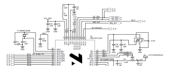
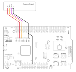
I have a custom board with LED on PIN 11 of nRF52832, and I am using SWD P20 configuration to program my board through nrf52 DK PCA10040. 
Apparently, nRFgo Studio find my custom board, so I want to blink the LED on my board using the blinky example. 

But when I upload the code to my board, nothing happens.

Here is the output of SES:

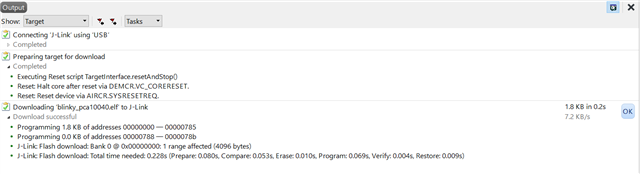
Here, what appear on nRFgo after loading the project: 

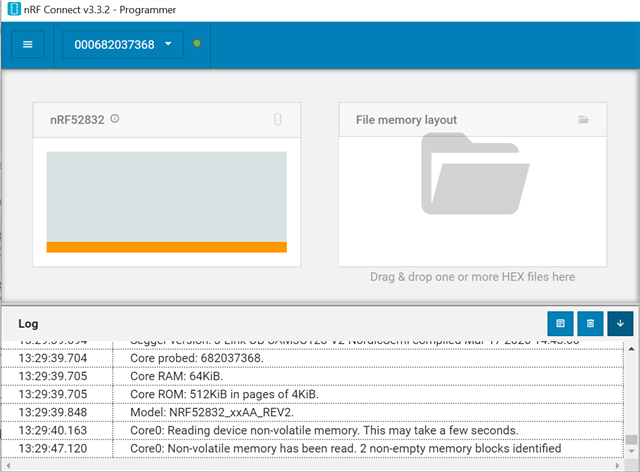
And before loading the program was like this:


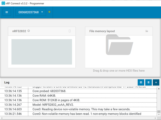
Do i need to create a custom_board.h? If so, why when I debug the example on SES, in boards.h the pca10040.h is still chosen instead of  custom_board.h?

What am I missing?

Thanks!

Alanarf 

  • Hi Alanarf

    Does your custom design include an external LF clock? If not, you'll need to modify the sdk_config.h file to use the internal LFRC oscillator instead by changing the following defines:

    // <h> Clock - SoftDevice clock configuration
    
    //==========================================================
    // <o> NRF_SDH_CLOCK_LF_SRC  - SoftDevice clock source.
     
    // <0=> NRF_CLOCK_LF_SRC_RC 
    // <1=> NRF_CLOCK_LF_SRC_XTAL 
    // <2=> NRF_CLOCK_LF_SRC_SYNTH 
    
    #ifndef NRF_SDH_CLOCK_LF_SRC
    #define NRF_SDH_CLOCK_LF_SRC 0
    #endif
    
    // <o> NRF_SDH_CLOCK_LF_RC_CTIV - SoftDevice calibration timer interval. 
    #ifndef NRF_SDH_CLOCK_LF_RC_CTIV
    #define NRF_SDH_CLOCK_LF_RC_CTIV 16
    #endif
    
    // <o> NRF_SDH_CLOCK_LF_RC_TEMP_CTIV - SoftDevice calibration timer interval under constant temperature. 
    // <i> How often (in number of calibration intervals) the RC oscillator shall be calibrated
    // <i>  if the temperature has not changed.
    
    #ifndef NRF_SDH_CLOCK_LF_RC_TEMP_CTIV
    #define NRF_SDH_CLOCK_LF_RC_TEMP_CTIV 2
    #endif
    
    // <o> NRF_SDH_CLOCK_LF_ACCURACY  - External clock accuracy used in the LL to compute timing.
     
    // <0=> NRF_CLOCK_LF_ACCURACY_250_PPM 
    // <1=> NRF_CLOCK_LF_ACCURACY_500_PPM 
    // <2=> NRF_CLOCK_LF_ACCURACY_150_PPM 
    // <3=> NRF_CLOCK_LF_ACCURACY_100_PPM 
    // <4=> NRF_CLOCK_LF_ACCURACY_75_PPM 
    // <5=> NRF_CLOCK_LF_ACCURACY_50_PPM 
    // <6=> NRF_CLOCK_LF_ACCURACY_30_PPM 
    // <7=> NRF_CLOCK_LF_ACCURACY_20_PPM 
    // <8=> NRF_CLOCK_LF_ACCURACY_10_PPM 
    // <9=> NRF_CLOCK_LF_ACCURACY_5_PPM 
    // <10=> NRF_CLOCK_LF_ACCURACY_2_PPM 
    // <11=> NRF_CLOCK_LF_ACCURACY_1_PPM 
    
    #ifndef NRF_SDH_CLOCK_LF_ACCURACY
    #define NRF_SDH_CLOCK_LF_ACCURACY 1
    #endif

    Best regards,

    Simon

  • Hi Simonr, 


    thanks for answer. 

    You mean the crystalls?The design includes two crystal oscillators, the 32.7 KHz and 32 MHz. I basically followed the circuit bellow.


  • Yes, I was aiming at the crystals, but they seem to be okay indeed. Thank you for the update.

    Have you configured the blinky example to use P0.11 instead of the LEDs configured in pca10040.h (P0.17-P0.20)? pca10040.h is likely chosen because you're using the chip on the DK which checks the BOARD_PCA10040) define in boards.h and uses the pca10040.h header file instead of your custom_board.h.

    Can you show me how your board custom board is connected to the NRF52DK debugger? Please use the picture below as reference when connecting your custom board to a DK's debugger.

    Best regards,

    Simon

  • Hi Simonr,


    Have you configured the blinky example to use P0.11 instead of the LEDs configured in pca10040.h (P0.17-P0.20)?

    I believe you are referring to these lines of pca10040.h right? 

    // LEDs definitions for PCA10040
    #define LEDS_NUMBER 4

    #define LED_START 17
    #define LED_1 17
    #define LED_2 18
    #define LED_3 11
    #define LED_4 20
    #define LED_STOP 20

    I changed LED_1 to 11, nothing happened on my board. 

    pca10040.h is likely chosen because you're using the chip on the DK

    Yeah, it makes sense hehe. Slight smile

    Can you show me how your board custom board is connected to the NRF52DK debugger?

    I am using this configuration, except that i am not shorting VDD and VTG, I am just using VTG. Couse, i am using external supply for my board, and i read that shorting it will make the DK power my board, but with 5V, and i need 3.3V.

    Thanks again! 

  • #define LED_3 11

    Actually i changed LED_3 as you can see, but again, nothing happened =/

Related