This post is older than 2 years and might not be relevant anymore
More Info: Consider searching for newer posts

How to correct the sampling time?

Dear everyone,

My platform is SDK16 and IDE is KEIL V5.25.

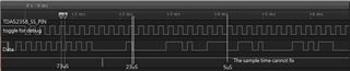
I set timer 2 to 104uS to sample a serial data. It isn't UART data, no start bit and stop bit.The start bytes are 0x55,0x55,0x01,0x01. But The sample time and data rate aren't very match. It cannot sample data correctly as attach picture. The function of tda5235_sample_handler is for correcting the sample time at falling edge of RX data. But it seems ineffective. I use a gpio of TDA5235B_SS_PIN (toggle it)  to debug the sample time. Could anyone guide me how to correct the sample time?

void m_timer2_event_handler(nrf_timer_event_t event_type, void *p_context)
{
    if (lf_rf_task.items.rssi_valid)
    {
        if (lf_rf_task.items.sync_rx == 1)
        {
            lf_rf_task.sample_rx_buf[lf_rf_task.sample_rx_len] &= ~1;
            nrf_gpio_pin_toggle(TDA5235B_SS_PIN);
            if (nrf_gpio_pin_read(TDA5235A_PP1_PIN))
                lf_rf_task.sample_rx_buf[lf_rf_task.sample_rx_len] |= 1;
            if (++lf_rf_task.sample_rx_bit >= 8)
            {
                lf_rf_task.sample_rx_bit = 0;
                if (++lf_rf_task.sample_rx_len >= 9)
                {
                    lf_rf_task.items.sync_rx = 0;
                    lf_rf_task.items.sample_rx_valid = 1;
                }
            }
            else
            {
                lf_rf_task.sample_rx_buf[lf_rf_task.sample_rx_len] <<= 1;
                lf_rf_task.items.sync_rx = 1;
            }
        }
        else
        {
            rrrr &= ~1;
            nrf_gpio_pin_toggle(TDA5235B_SS_PIN);
            if (nrf_gpio_pin_read(TDA5235A_PP1_PIN))
                rrrr |= 1;
            if (++lf_rf_task.sample_rx_bit >= 24)
            {
                if ((rrrr & 0xffffff) == 0x550101)
                {
                    // sync received
                    lf_rf_task.sample_rx_len = 0;
                    lf_rf_task.sample_rx_bit = 0;
                    lf_rf_task.items.sync_rx = 1;
                }
                else
                {
                    rrrr <<= 1;
                    lf_rf_task.sample_rx_bit--;
                }
            }
        }
    }
    else
    {
        // rssi just under threshole, clear counter
        lf_rf_task.items.sync_rx = 0;
    }
    nrf_drv_saadc_sample();
}

void tda5235_sample_handler(nrf_drv_gpiote_pin_t pin, nrf_gpiote_polarity_t action)
{
    NRF_TIMER2->TASKS_COUNT = 100; //  it is ineffective.
}

static void tda5235_gpio_init(void)
{
    ret_code_t err_code;

    nrf_gpio_cfg_input(TDA5235A_PP1_PIN, NRF_GPIO_PIN_PULLUP);
    nrf_gpio_cfg_input(TDA5235A_PP2_PIN, NRF_GPIO_PIN_PULLUP);

    nrf_drv_gpiote_in_config_t in_config = GPIOTE_CONFIG_IN_SENSE_HITOLO(true);
    in_config.pull = NRF_GPIO_PIN_PULLUP;
    err_code = nrf_drv_gpiote_in_init(TDA5235A_PP2_PIN, &in_config, tda5235_int_handler);
    APP_ERROR_CHECK(err_code);
    nrf_drv_gpiote_in_event_enable(TDA5235A_PP2_PIN, true);

    // for data sample correction
    err_code = nrf_drv_gpiote_in_init(TDA5235A_PP1_PIN, &in_config, tda5235_sample_handler);
    APP_ERROR_CHECK(err_code);
    nrf_drv_gpiote_in_event_enable(TDA5235A_PP1_PIN, true);
}

  • Ted,

    I think you misunderstood how the Timer works.

    void tda5235_sample_handler(nrf_drv_gpiote_pin_t pin, nrf_gpiote_polarity_t action)
    {
        NRF_TIMER2->TASKS_COUNT = 100; //  it is ineffective.
    }

    TASKS_COUNT does not take the count of the counter to a number after which you expect a timeout. All TASKS_XXX in the nRF device only take a value of 1. It means that for 1, trigger that particular task. When you are writing 100 to TASKS_COUNT you are basically trying to write binary 1100100 into it. Since it is only 1 bit register, you are effectively writing 0 into it. And this TASKS only work in COUNTER mode.

    I guess what you are trying to do is to get a timer callback after 100 ticks. If that is what you are trying to do then probably you need to set this in TIMER2->CC register and restart the timer.

    I strongly suggest you not to access the registers of the timers directly and use the timer library instead.

  • The unit of timer library is in mini-second. I cannot use timer library, because my sample time is 104uS. It more faster than the functions they was provided by timer library. I change TIMER2->CC register and set it back to 0x680 (104uS) for next sampling. The data still cannot be read correctly. Do you have any suggestions?

    void tda5235_sample_handler(nrf_drv_gpiote_pin_t pin, nrf_gpiote_polarity_t action)
    {
    NRF_TIMER2->CC[0] = 0x240;     // --> correct time, after falling edge of data.
    NRF_TIMER2->TASKS_CLEAR = 1;
    lf_rf_task.items.rewrite_sample_time = 1;
    }

    void m_timer2_event_handler(nrf_timer_event_t event_type, void* p_context)
    {
    if(lf_rf_task.items.rewrite_sample_time == 1)
    {
    NRF_TIMER2->CC[0] = 0x680;   //set it back to 0x680 (104uS)
    NRF_TIMER2->TASKS_CLEAR = 1;
    lf_rf_task.items.rewrite_sample_time = 0;
    ......

    }

  • The unit of timer library is in mini-second. I cannot use timer library, because my sample time is 104uS. It more faster than the functions they was provided by timer library. I change TIMER2->CC register and set it back to 0x680 (104uS) for next sampling. The data still cannot be read correctly. The duration between gpio interrupt generates and interrupt service subroutine is around 20uS. So change the register of NRF_TIMER2->CC cannot sample data at 104us correctly. Do you have any suggestions?

    void tda5235_sample_handler(nrf_drv_gpiote_pin_t pin, nrf_gpiote_polarity_t action)
    {
    NRF_TIMER2->CC[0] = 0x240;     // --> correct time, after falling edge of data.
    NRF_TIMER2->TASKS_CLEAR = 1;
    lf_rf_task.items.rewrite_sample_time = 1;
    }

    void m_timer2_event_handler(nrf_timer_event_t event_type, void* p_context)
    {
    if(lf_rf_task.items.rewrite_sample_time == 1)
    {
    NRF_TIMER2->CC[0] = 0x680;   //set it back to 0x680 (104uS)
    NRF_TIMER2->TASKS_CLEAR = 1;
    lf_rf_task.items.rewrite_sample_time = 0;
    ......

    }

  • I change the mode of timer 2 to counter. But it cannot generate an interrupt. How to make it to generate an interrupt at count mode?

    void lf_rf_timer_init(void)
    {
    uint32_t err_code = NRF_SUCCESS;

    // setup timer parameter
    nrf_drv_timer_config_t timer_cfg = {
    .frequency = (nrf_timer_frequency_t)NRFX_TIMER_DEFAULT_CONFIG_BIT_WIDTH,
    .mode = (nrf_timer_mode_t)NRF_TIMER_MODE_COUNTER,
    .bit_width = (nrf_timer_bit_width_t)NRF_TIMER_BIT_WIDTH_32,
    .interrupt_priority = 5, // more high priority, default is 6
    .p_context = NULL
    };
    // setup timer 2 to count mode for RF sampling
    err_code = nrf_drv_timer_init(&m_timer2, &timer_cfg, m_timer2_event_handler);
    APP_ERROR_CHECK(err_code);

    // RF data sample interrupt
    nrf_drv_timer_extended_compare(
    &m_timer2, NRF_TIMER_CC_CHANNEL0, nrf_drv_timer_us_to_ticks(&m_timer2, us), NRF_TIMER_SHORT_COMPARE0_CLEAR_MASK, true);
    nrf_drv_timer_enable(&m_timer2);
    }

Related