This post is older than 2 years and might not be relevant anymore
More Info: Consider searching for newer posts

Bootloader WDT not Firing

Hi,

I am still investigating this but, I think it is best that we discuss it on this forum. 

I am using SDK 16.0.0, nRF52840, secure_bootloader_usb on a custom board. The problem appears to be the following:

My application is using the WDT to provide a means of system reset within 10 seconds if WDT is not refreshed. 

I am entering DFU by causing a writing to GPREGRET 0xB1 and causing a softreset with the purpose of downloading firmware via USB. 

At this point the bootloader takes control and should be able to identify that the WDT was running in the application and hence keep feeding it. 

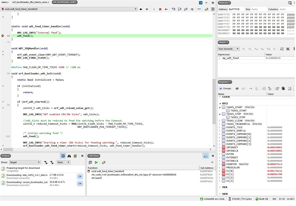
Indeed, the bootloader checks for the enabled WDT and normally should enable RTC2 as a WDT refresh timer. 

What we are finding is that (at least in the release version of the bootloader) this is not happening. 

For some reason, the RTC2 interrupts are for Channel 2 (and Channel 1) compare are not enabled and the task of is also not enabled. The result is that the MCU is reset from the running WDT. 

Now comes the good part:

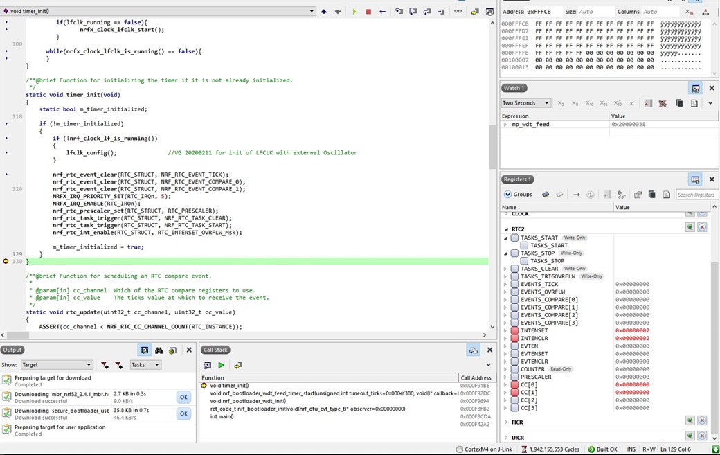
Trying to identify why this is happening we were setting breakpoints to various locations and checking what the firmware was doing. We found that in the file nrf_bootloader_dfu_timers and in the code shown below, a break point right at if(!m_timer_initialized) would do the trick.

/**@brief Function for initializing the timer if it is not already initialized.
 */
static void timer_init(void)
{
    static bool m_timer_initialized;

    if (!m_timer_initialized)
    {
        if (!nrf_clock_lf_is_running())
        {
            //nrf_clock_lf_src_set(NRF_CLOCK_LFCLK_Xtal_Full_Swing);      //Added VG 20200213
            //nrf_clock_task_trigger(NRF_CLOCK_TASK_LFCLKSTART);
            //while(nrf_clock_lf_is_running() == false){}                 //Added VG 20200213 Wait till LFCLK Initializes

            lfclk_config();

        }
                        
        nrf_rtc_event_clear(RTC_STRUCT, NRF_RTC_EVENT_TICK);
        nrf_rtc_event_clear(RTC_STRUCT, NRF_RTC_EVENT_COMPARE_0);
        nrf_rtc_event_clear(RTC_STRUCT, NRF_RTC_EVENT_COMPARE_1);
        NRFX_IRQ_PRIORITY_SET(RTC_IRQn, 5);
        NRFX_IRQ_ENABLE(RTC_IRQn);
        nrf_rtc_prescaler_set(RTC_STRUCT, RTC_PRESCALER);
        nrf_rtc_task_trigger(RTC_STRUCT, NRF_RTC_TASK_CLEAR);
        nrf_rtc_task_trigger(RTC_STRUCT, NRF_RTC_TASK_START);
        nrf_rtc_int_enable(RTC_STRUCT, RTC_INTENSET_OVRFLW_Msk);

        m_timer_initialized = true;
    }
}

When a break point is placed there, then after continuing code execution, the RTC2 timer starts normally and the interrupt CC2 is enabled. As a concsequence the WDT running is reset by RTC2 feed action. Breakpoints after this location in the code DO NOT have any effect. The RTC2 is not initialized correctly and does not feed the WDT. 

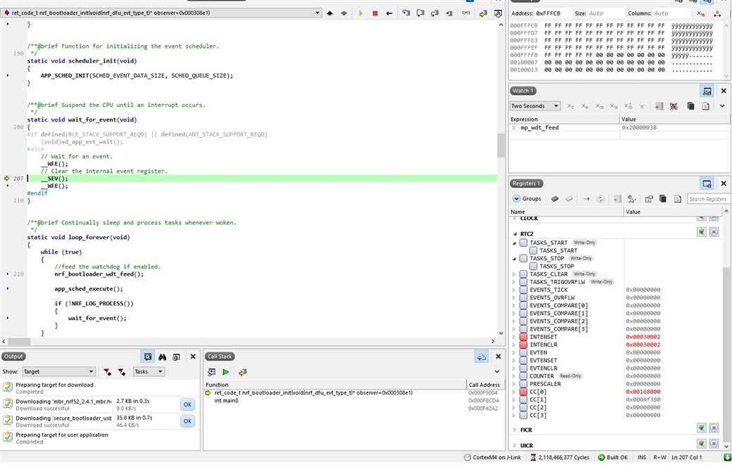
We cannot, at the moment, explain this behavior. Best guess is that it has do to with the way the code is written because the same routines are used to initialize the inactivity timer used by the bootloader. 

We will keep investigating but any help is greatly appreciated. 

Thanks.

Parents Reply Children
  • Hello Einar,

    Thanks for comming back so quickly. It is odd and what is frustrating is why a breakpoint allows the RTC2 to be triggered. 

    Indeed I did some changes to the bootloader but I cannot see how these may affect it. Let me explain:

    In the file nrf_bootloader_dfu_timers I needed to change the way the LFCLK is initialized because I am using an external oscillator and not a crystal. The routine timer_init has been modified to:

    /**@brief Function for initializing the timer if it is not already initialized.
     */
    static void timer_init(void)
    {
        static bool m_timer_initialized;
            
        if (!m_timer_initialized)
        {
            if (!nrf_clock_lf_is_running())
            {           
                lfclk_config();            
            }
                                   
            nrf_rtc_event_clear(RTC_STRUCT, NRF_RTC_EVENT_TICK);
            nrf_rtc_event_clear(RTC_STRUCT, NRF_RTC_EVENT_COMPARE_0);
            nrf_rtc_event_clear(RTC_STRUCT, NRF_RTC_EVENT_COMPARE_1);
            NRFX_IRQ_PRIORITY_SET(RTC_IRQn, 5);
            NRFX_IRQ_ENABLE(RTC_IRQn);
            nrf_rtc_prescaler_set(RTC_STRUCT, RTC_PRESCALER);
            nrf_rtc_task_trigger(RTC_STRUCT, NRF_RTC_TASK_CLEAR);
            nrf_rtc_task_trigger(RTC_STRUCT, NRF_RTC_TASK_START);
            nrf_rtc_int_enable(RTC_STRUCT, RTC_INTENSET_OVRFLW_Msk);
                    
            m_timer_initialized = true;
        }
    }

    where the routine lfclk_config is the following:

    static void lfclk_config(void)
    {      
        bool lfclk_running=	nrfx_clock_lfclk_is_running();
         	                  
             NRF_CLOCK->LFCLKSRC = LFCLKSRC_XTERNAL_OSCILLATOR;  
            
             if(lfclk_running == false){
               	nrfx_clock_lfclk_start();
             }
          
          while(nrfx_clock_lfclk_is_running() == false){
          }
    }

    Another minor modification is in the nrf_bootloader.c file where I introduced a port initialization in the nrf_dfu_init_user routine as shown below:

    /**@brief Weak implementation of nrf_dfu_init
     *
     * @note    This function must be overridden in application if
     *          user-specific initialization is needed.
     */
    __WEAK uint32_t nrf_dfu_init_user(void)
    {
        NRF_LOG_DEBUG("in weak nrf_dfu_init_user");
    
        ports_init();                                     
    
        return NRF_SUCCESS;
    }

    ports_init only intializes input and output ports for our custom board

    Also in the file nrf_dfu_req_handler.c I added a bit of code for toggling an LED inside the dfu_req_handler as shown below:

    static void nrf_dfu_req_handler_req(void * p_evt, uint16_t event_length)
    {
        nrf_dfu_request_t * p_req = (nrf_dfu_request_t *)(p_evt);
        nrf_dfu_req_handler_req_process(p_req);
        nrf_gpio_pin_toggle(LED_RED);                                                 
    }

    This toggles an LED. 

    Finally in main.c I only added toggling of LEDs where needed as shown below:

    static void dfu_observer(nrf_dfu_evt_type_t evt_type)
    {
        switch (evt_type)
        {
            case NRF_DFU_EVT_DFU_FAILED:
            case NRF_DFU_EVT_DFU_ABORTED:
            case NRF_DFU_EVT_DFU_INITIALIZED:
    
                //bsp_board_init(BSP_INIT_LEDS);
                //bsp_board_led_on(BSP_BOARD_LED_0);
                //bsp_board_led_on(BSP_BOARD_LED_1);
                //bsp_board_led_off(BSP_BOARD_LED_2);
                nrf_gpio_pin_clear(LED_GRN);
                nrf_gpio_pin_clear(LED_RED);
                break;
            case NRF_DFU_EVT_TRANSPORT_ACTIVATED:
                //bsp_board_led_off(BSP_BOARD_LED_1);
                //bsp_board_led_on(BSP_BOARD_LED_2);            
                nrf_gpio_pin_set(LED_RED);            
                break;
            case NRF_DFU_EVT_DFU_STARTED:            
                break;
    
            default:
                break;
        }
    }

    I cannot see how, these modifications could affect the triggering of RTC2. 

    Meanwhile I tried using RTC1 or RTC0 but the result is the same. I also tried to introduce nrfx driver for the RTC and trigger it with the nrfx driver rather than the RTC HAL and this did not have any effect. 

    Let me know of your opinion. 

  • Hi,

    This is still a puzzle to me. The RTC obviously runs of the 32.768 kHz clock, which uses an external oscillator in your case. That should be OK, and no matter how that behaves, the RTC configuration should be unaffected. You could think that the external oscillator was not properly up and running when you configured the RTC, but the order there does not matter.

    Some more questions:

    • How have you verified hat the RTC interrupts are not enabled? Can you show a screenshot or register dump of the RTC registers showing the states when it should be up and running? Preferably both when it works (with your breakpoint present) and without it.
    • What happens if you replace the breakpoint with a short delay, does that have any effect?
    • What happens if you don't start the WDT before entering the bootloader (and keep it not running), but modify line 89 in nrf_bootloader_wdt.c to keep the behavior of feeding it, etc as is. Does the regular feeding work as expected in this case? (I wonder if the fact that the WDT forces the LFCLK on could cause problems when you reconfigure it to use an external oscillator, though I do not have any particular reason for thinking that it should).
  • Hello Einar, 

    I know. It is a puzzle and very frustrating. It shouldn't be happening. I know that the LFCLK is running normally in both cases because in the correct situation (where RTC2 is running), the bootloader will reset the MCU after 45 seconds of inacitivity (this is the time I have set) and in the incorrect case (where RTC2 is not running) the MCU resets within 10 seconds (more or less) which is the WDT interval. 

    Let me answer your questions

    1) The interrupts of the RTC are enabled. What is happening is that the RTC2 is not running in the problematic case. I am deducing this by looking at the RTC2 registers. Look below, the case where the RTC2 is running:

    Above, I stopped the execution in the wdt_feed to show the result. 

    Look now below the problematic case:

    In the 2 pictures above, the breakpoint was set after the if(!m_timer_initialized) at the end of the timer_init routine. You can see that only the overflow interrupt is set and the counter is not running. 

    To further show the effect I just paused the debug inside the sleep loop (image 2) where again you can see all interrupts set on RTC2, the CC registers have been filled but the counter is 0. The RTC is not running. 

    2) I tried delays in various points in the code. I tried small and large delays. None of them works. The effect is always the same. RTC2 is not running

    3) To do what you asked, I disabled the application WDT and modified nrf_bootloader_wdt_init routine as follows:

    void nrf_bootloader_wdt_init(void)
    {
        static bool initialized = false;
    
        if (initialized)
        {
            return;
        }
    
        //if (nrf_wdt_started())
        //{
            uint32_t wdt_ticks = 0x50000;//nrf_wdt_reload_value_get();
    
            NRF_LOG_INFO("WDT enabled CRV:%d ticks", wdt_ticks);
    
            //wdt_ticks must be reduced to feed the watchdog before the timeout.
            uint32_t reduced_timeout_ticks = MAX((int32_t)wdt_ticks - MAX_FLASH_OP_TIME_TICKS,
                                                 NRF_BOOTLOADER_MIN_TIMEOUT_TICKS);
    
            /* initial watchdog feed */
            wdt_feed();
    
            NRF_LOG_INFO("Starting a timer (%d ticks) for feeding watchdog.", reduced_timeout_ticks);
            nrf_bootloader_wdt_feed_timer_start(reduced_timeout_ticks, wdt_feed_timer_handler);
    
            NVIC_EnableIRQ(WDT_IRQn);
        //}
        //else
        //{
        //    NRF_LOG_INFO("WDT is not enabled");
        //}
    
        initialized = true;
    }

    This enables the WDT inside the bootloader. 

    In this case, the RTC2 actually WORKS. I can see the RTC2 counter running no matter if a place a breakpoint or not at any location. 

    So it seems that something is fishy with the fact that an enabled WDT changes configuration to LFCLK inside the bootloader. It seems to be ok when LFCLK and WDT are both enabled inside the bootloader. 

    Any ideas?

    Thanks.

  • Hi,

    I need to try to reproduce this on my side and discuss it with my colleagues. At this point, I fail to understand what could be happening here.

    Is simply not using the external LF clock when in the bootloader a viable workaround?

    In the meantime, I want to mention a point which may not be directly related to this issue, but maybe worth noting. Since the WDT forces the LFCLK on, and the WDT is not reset by a soft reset but the clock configuration is, the LFRC clock is running after reset. This means that when you configure it to run on the external reference, you are violating this statement in the clock chapter in the product specification: "It is not allowed to write to register LFCLKSRC when the LFCLK is running.". Violating this should normally not be a big issue (and it is in fact quite common, though you will trigger erratum 101).

  • Hello Einar,

    I tried what you suggested in the following:

    /**@brief Function for initializing the timer if it is not already initialized.
     */
    static void timer_init(void)
    {
        static bool m_timer_initialized;
            
        if (!m_timer_initialized)
        {
            /*if (!nrf_clock_lf_is_running())
            {           
                lfclk_config();               //VG 20200211 for init of LFCLK with external Oscillator
            }*/
                                   
            nrf_rtc_event_clear(RTC_STRUCT, NRF_RTC_EVENT_TICK);
            nrf_rtc_event_clear(RTC_STRUCT, NRF_RTC_EVENT_COMPARE_0);
            nrf_rtc_event_clear(RTC_STRUCT, NRF_RTC_EVENT_COMPARE_1);
            NRFX_IRQ_PRIORITY_SET(RTC_IRQn, 5);
            NRFX_IRQ_ENABLE(RTC_IRQn);
            nrf_rtc_prescaler_set(RTC_STRUCT, RTC_PRESCALER);
            nrf_rtc_task_trigger(RTC_STRUCT, NRF_RTC_TASK_CLEAR);
            nrf_rtc_task_trigger(RTC_STRUCT, NRF_RTC_TASK_START);
            nrf_rtc_int_enable(RTC_STRUCT, RTC_INTENSET_OVRFLW_Msk);
                    
            m_timer_initialized = true;
        }
    }

    Indeed after reset, the LFCLKL shoul be running using the internal RC oscillator. So I tried not to initialize the LFCLK but let it run in RC mode. 

    The result is the same. The LFCLK should be running because I get a WDT reset after 10 seconds. The RTC2 IS NOT running no matter where I place the breakpoint. I can see the interrupts and CC registers initialized but the counter is not measuring hence the WDT causes a reset.

    Any ideas are welcome. What is Errata 101? I tried looking in nRF52840 documentation but could not find 101.

    Thanks.

Related