This post is older than 2 years and might not be relevant anymore
More Info: Consider searching for newer posts

Using nRF5340-PDK with zephyr adxl372 sensor sample project

I'm new to the nRF5340 and zephyr and ncs, but I have gone through the tutorial series https://devzone.nordicsemi.com/nordic/nrf-connect-sdk-guides/b/getting-started/posts/nrf-connect-sdk-tutorial 

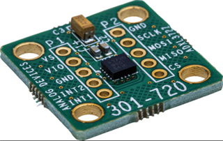
We're developing a product that will use the SPIS peripheral on the nRF5340 and I have a few nRF5340-PDK boards

Since I haven't found any SPIS sample projects, I started with the zephyr adxl372 sensor sample project.

I wanted to get it to a point where the SPIM peripheral was working (wiggling pins as expected) then create my own sensor and change it to SPIS.

I re-mapped the SPI pins to pins on port 1.

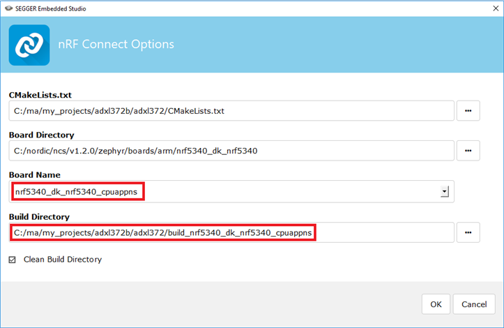
I started by using the non-secure build, but couldn't get any SPI activity on the pins.

It looked like the chip select pin was being handled as a GPIO pin (rather than as part of the SPIM peripheral) and when I tried to manually change registers in the GPIO1 peripheral through the SES through the registers view, all the SPIM1 registers showed as 0 and I couldn't change them.

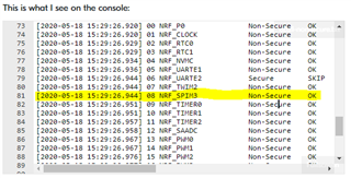
I wondered if GPIO1 was not under the application processor's control, because the NRF_P1 is missing from the peripheral domain status printed at bootup.

Peripheral Domain Status
00 NRF_P0 Non-Secure OK
01 NRF_CLOCK Non-Secure OK
02 NRF_RTC0 Non-Secure OK
03 NRF_RTC1 Non-Secure OK
04 NRF_NVMC Non-Secure OK
05 NRF_UARTE1 Non-Secure OK
06 NRF_UARTE2 Secure SKIP
07 NRF_TWIM2 Non-Secure OK
08 NRF_SPIM3 Non-Secure OK
09 NRF_TIMER0 Non-Secure OK
10 NRF_TIMER1 Non-Secure OK
11 NRF_TIMER2 Non-Secure OK
12 NRF_SAADC Non-Secure OK
13 NRF_PWM0 Non-Secure OK
14 NRF_PWM1 Non-Secure OK
15 NRF_PWM2 Non-Secure OK
16 NRF_PWM3 Non-Secure OK
17 NRF_IPC Non-Secure OK
18 NRF_VMC Non-Secure OK
19 NRF_FPU Non-Secure OK
20 NRF_EGU1 Non-Secure OK
21 NRF_EGU2 Non-Secure OK
22 NRF_DPPIC Non-Secure OK
23 NRF_GPIOTE1 Non-Secure OK
24 NRF_REGULATORS Non-Secure OK

When I choose Project > Configure nRF Connect SDK Project (in the non-secure project) it shows two options - menuconfig and spm_menuconfig

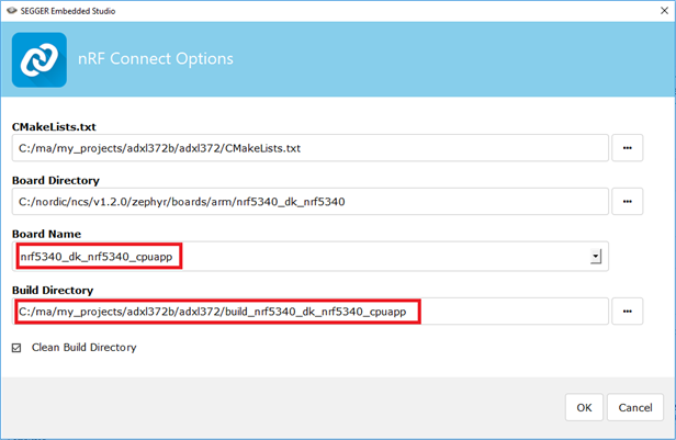
I tried the secure build, and then I saw SPI activity.

But when I try to view the configuration with Project > Configure nRF Connect SDK Project (in the secure project) it does not show me two options.  It just takes me to a config.

Q1:  Why doesn't the non-secure project work to control the SPI pins?

Q2: Why doesn't the secure project show both menuconfig and spm_menuconfig?

Parents
  • Hi Douglas,

    Q1:

    Looking at the pins you have selected, 26,27 and 28 should be OK, but you have selected the same pin (p1.05) for both CS and int1. ( They are not the same )

    One other thing you should notice is that to use the adxl372 driver you need to connect to a adxl372. Since it is a init function that runs in the beginning and check if the device is connected. (if not the "device_get_binding()" will fail)

    Q2:

    When you build a regular application, you build it for the non-secure area as described in the document "working with nrf9160".
    But you also build "Secure Partition Manager" at the same time, which is why both the "menuconfig" for your application and "spm_menuconfig" shows when you try to configure something building an application in the "non-secure" area.

  • Q1:

    I understand that if I want to fully use the adxl372 example program (get accelerometer readings, etc.) I would need to connect an adxl372.

    But I'm just trying to get the SPI port operating.

    Once I get the SPI port operating, I'm going to change the example code to not use the adxl372 but to accomodate what we're doing on our board.

    I'm looking at the SPI signals (cs, sck, mosi, miso) with an oscilloscope and looking for data to be sent over the SPI bus.

    I understand that without an adxl372 connected, device_get_binding() will fail, but it should attempt to read a few registers over the SPI bus before concluding that the adxl372 is not connected.  I should see those register reads on the oscilloscope.

    When I build and run a non-secure application

    This is what I see on the console:

    1
    2
    3
    4
    5
    6
    7
    8
    9
    10
    11
    12
    13
    14
    15
    16
    17
    18
    19
    [2020-05-18 15:29:26.692] *** Booting Zephyr OS build v2.1.99-ncs1 ***
    [2020-05-18 15:29:26.697] Flash region Domain Permissions
    [2020-05-18 15:29:26.700] 00 0x00000 0x08000 Secure rwxl
    [2020-05-18 15:29:26.702] 01 0x08000 0x10000 Non-Secure rwxl
    [2020-05-18 15:29:26.706] 02 0x10000 0x18000 Non-Secure rwxl
    [2020-05-18 15:29:26.709] 03 0x18000 0x20000 Non-Secure rwxl
    [2020-05-18 15:29:26.714] 04 0x20000 0x28000 Non-Secure rwxl
    [2020-05-18 15:29:26.716] 05 0x28000 0x30000 Non-Secure rwxl
    [2020-05-18 15:29:26.719] 06 0x30000 0x38000 Non-Secure rwxl
    [2020-05-18 15:29:26.723] 07 0x38000 0x40000 Non-Secure rwxl
    [2020-05-18 15:29:26.726] 08 0x40000 0x48000 Non-Secure rwxl
    [2020-05-18 15:29:26.729] 09 0x48000 0x50000 Non-Secure rwxl
    [2020-05-18 15:29:26.733] 10 0x50000 0x58000 Non-Secure rwxl
    [2020-05-18 15:29:26.736] 11 0x58000 0x60000 Non-Secure rwxl
    [2020-05-18 15:29:26.739] 12 0x60000 0x68000 Non-Secure rwxl
    [2020-05-18 15:29:26.742] 13 0x68000 0x70000 Non-Secure rwxl
    [2020-05-18 15:29:26.746] 14 0x70000 0x78000 Non-Secure rwxl
    [2020-05-18 15:29:26.749] 15 0x78000 0x80000 Non-Secure rwxl
    [2020-05-18 15:29:26.752] 16 0x80000 0x88000 Non-Secure rwxl
    XXXXXXXXXXXXXXXXXXXXXXXXXXXXXXXXXXXXXXXXXXXXXXXXXX

    Using the debugger in SES, I can see that the code execution is getting to adxl372_init() and running adxl372_probe() and adxl372_reg_read().  It appears to get stuck in z_impl_spi_transceive().

    On the oscilloscope, I've tried triggering on CS going low, SCK going low, and MOSI going low.  None of these signals are changing state while running the non-secure app.

    HOWEVER, if I build and run the app as secure:

    This is what I see on the console:

    1
    2
    3
    [2020-05-18 16:00:20.338] *** Booting Zephyr OS build v2.1.99-ncs1 ***
    [2020-05-18 16:00:20.342] Could not get ADXL372 device
    [2020-05-18 16:00:21.335] [00:00:00.000,000] <err> ADXL372: failed to read id (0x0:0x0)
    XXXXXXXXXXXXXXXXXXXXXXXXXXXXXXXXXXXXXXXXXXXXXXXXXX

    and the oscilloscope triggers.  I see the nRF5340 send 0x01 0xFF 0x05 0xFF over the SPI bus (on MOSI).

    So I'm trying to understand why the secure app is actually sending SPI bytes but the non-secure app is not.

    It's not preventing me from moving on, but since I'm new to the nRF Connect SDK and zephyr and the nRF5340 I'm trying to better understand the issues with using them.

    By the way, I've changed the overlay files to separate the CS and interrupt pins.  This doesn't seem to affect the behavior described above.

    Here's my updated project

    adxl372-20200518.zip

  • Hi,
    If you are trying out just the SPI, I would rather recommend you checking out a simple SPI sample --> https://github.com/Rallare/fw-nrfconnect-nrf/tree/nrf9160_samples/samples/nrf9160/spi that shows how you can implement and use it.

    Just change the .overlay file to suit your nrf5340 and your chosen pins.

    The reason it's working when building the application in the Secure area, is because then you have the SPI 1 available to be used. If you look at the "Secure Partition Manager" when building the application for the non-secure area you see that you only have enabled SPI 3 to be used in the non-secure area:

    Not all peripherals have been set to new available by default in the non-secure area.

    However, there is a Pull request to fix that:https://github.com/NordicPlayground/fw-nrfconnect-nrf/pull/1896

    So either change the device tree file (.overlay file) + prj.conf (configuration file) file to use SPI 3 or

    change the nrf/subsys/spm files "Kconfig" and "spm.c" with these additional lines so you get access to the SPI_1 in the non-secure area.

    Kconfig

    spm.c

    Br,

    Martin L.

  • According to the errata, SPI_3 does not work on nRF5340, so I tried the other option.

    I added these lines to nrf/subsys/spm/Kconfig

    config SPM_NRF_P1_NS
    bool "GPIO is Non-Secure"
    default y

    config SPM_NRF_SPIM1_NS
    bool "SPIM1 is Non-Secure"
    default y

    I added these lines to nrf/subsys/spm/spm.c

    #ifdef NRF_P1
    PERIPH("NRF_P1", NRF_P1, CONFIG_SPM_NRF_P1_NS),
    #endif

    #ifdef NRF_SPIM1
    PERIPH("NRF_SPIM1", NRF_SPIM1, CONFIG_SPM_NRF_SPIM1_NS),
    #endif

    But I still don't get any SPI activity on the non-secure build.

    Did I miss something?

    I also tried the other SPI example you provided, but it looks like the formatting of the nRF Connect SDK has changed a lot since that example was written.  I tried fixing each issue as I got warning messages, but I wasn't able to get the secure build to build successfully, and the non-secure build does not produce any SPI activity.

    Here is the current state of that sample project (with my edits)

    spi-20200519.zip

  • I managed to get your modified SPI sample from Rallare SPI sample to work. I did the following to make it work:

    • Started with the SPI sample you uploaded in your latest reply
    • Removed CONFIG_TRUSTED_EXECUTION_NONSECURE=y from prj.conf
    • Changed the pin values in nrf5340_dk_nrf5340_cpuapp.overlay from hexadecimal format into decimal format:

    Fullscreen
    1
    2
    3
    4
    5
    6
    7
    8
    9
    10
    11
    12
    13
    &spi1 {
    status = "okay";
    compatible = "nordic,nrf-spim";
    sck-pin = <26>; //sck-pin = <0x26>;
    //Had to use pin 30 since pin 28 was not accessible on my nRF53DK for some reason
    mosi-pin = <30>; //mosi-pin = <0x28>;
    miso-pin = <27>; //miso-pin = <0x27>;
    cs-gpios = <&gpio1 5 0>;
    clock-frequency = <4000000>;
    };
    &spi2 {
    status = "disabled";
    };
    XXXXXXXXXXXXXXXXXXXXXXXXXXXXXXXXXXXXXXXXXXXXXXXXXX

    • Then I connected P0.27 with P0.30 on the nRF53 DK
    • Built the sample, turned on the nRF53 DK, and flashed it.

    If it works, you should see the following log:

    Fullscreen
    1
    2
    3
    4
    5
    6
    7
    8
    9
    10
    11
    12
    13
    14
    15
    16
    17
    18
    19
    20
    21
    *** Booting Zephyr OS build v2.1.99-ncs1 ***
    SPIM Example
    TX sent: 0
    RX recv: 0
    TX sent: 1
    RX recv: 1
    TX sent: 2
    RX recv: 2
    TX sent: 3
    RX recv: 3
    TX sent: 4
    RX recv: 4
    TX sent: 5
    RX recv: 5
    TX sent: 6
    RX recv: 6
    TX sent: 7
    RX recv: 7
    TX sent: 8
    RX recv: 8
    TX sent: 9
    XXXXXXXXXXXXXXXXXXXXXXXXXXXXXXXXXXXXXXXXXXXXXXXXXX

    Best regards,

    Simon


    Here is the working sample: spi.zip

  • With the changes you suggested, I was able to get the SPI sample from Rallare SPI sample to work as you described.

    It seems like your step "Removed CONFIG_TRUSTED_EXECUTION_NONSECURE=y from prj.conf" was necessary to get the secure build to build successfully.

    I don't understand why it was necessary to change the pins.  I had planned to use:

    CS: P1.05

    SCK: P1.06

    MISO: P1.07

    MOSI: P1.08

    Which you changed to:

    CS: P1.05

    SCK: P0.26

    MISO: P0.27

    MOSI: P0.30

    But why was this change necessary?

    The modified adxl372 example (secure build) I mentioned above uses the original pins successfully.

    By the way, the CS pin did not go low during transmissions even after implementing your changes, so is there some problem with the sample code that makes port 1 pins not work?  (You have to use port 0?)

    I also don't understand why the non-secure builds for the SPI sample or the adxl372 sample don't produce any SPI activity on the SPI port.

    Can you provide any insight?

  • DBT said:
    I don't understand why it was necessary to change the pins.  I had planned to use:

    No, that shouldn't be necessary. Just forget my comment about that.


    Have you seen this ticket, where a colleague has provided a working modified version of rallare SPI using SPI_1 and the non-secure version of the board (nrf5340_dk_nrf5340_cpuappns).

    It seems like you have to disable i2c1 in the overlay file.

    Best regards,

    Simon

Reply
  • DBT said:
    I don't understand why it was necessary to change the pins.  I had planned to use:

    No, that shouldn't be necessary. Just forget my comment about that.


    Have you seen this ticket, where a colleague has provided a working modified version of rallare SPI using SPI_1 and the non-secure version of the board (nrf5340_dk_nrf5340_cpuappns).

    It seems like you have to disable i2c1 in the overlay file.

    Best regards,

    Simon

Children
  • OK if I download the rallare_spi.zip file from the link you provided, it seems to work as-is with a non-secure build.

    If I try to change the SPI pins to the ones I want to use, it stops working.  Do you have any insight?

    Fullscreen
    1
    2
    3
    4
    5
    6
    7
    8
    9
    10
    11
    12
    13
    14
    15
    16
    17
    18
    19
    20
    21
    nrf5340_dk_nrf5340_cpuappns.overlay
    BEFORE
    &spi1 {
    compatible = "nordic,nrf-spim";
    status = "ok";
    mosi-pin = <4>;
    miso-pin = <5>;
    sck-pin = <6>;
    };
    &spi2 {
    status = "disabled";
    };
    &i2c1 {
    status = "disabled";
    };
    XXXXXXXXXXXXXXXXXXXXXXXXXXXXXXXXXXXXXXXXXXXXXXXXXX

  • The reason it isn't working with the SPI pins you're using is that there are only 32 valid pin select option, specifically between 0 and 31.

    You've chosen the values 0x28, 0x27 and 0x26 which converts to the decimal values 40, 39, and 38. Check out the file ncs\nrf\samples\other\rallare_spi\build\zephyr\include\generated\devicetree.conf after building the sample with those pins:

    Fullscreen
    1
    2
    3
    4
    5
    6
    7
    8
    9
    10
    11
    12
    13
    14
    15
    # SCK pin
    DT_NORDIC_NRF_SPIM_40009000_SCK_PIN=38
    DT_ALIAS_SPI_1_SCK_PIN=38
    DT_NORDIC_NRF_SPIM_SPI_1_SCK_PIN=38
    DT_INST_0_NORDIC_NRF_SPIM_SCK_PIN=38
    # MOSI pin
    DT_NORDIC_NRF_SPIM_40009000_MOSI_PIN=40
    DT_ALIAS_SPI_1_MOSI_PIN=40
    DT_NORDIC_NRF_SPIM_SPI_1_MOSI_PIN=40
    DT_INST_0_NORDIC_NRF_SPIM_MOSI_PIN=40
    # MISO pin
    DT_NORDIC_NRF_SPIM_40009000_MISO_PIN=39
    DT_ALIAS_SPI_1_MISO_PIN=39
    DT_NORDIC_NRF_SPIM_SPI_1_MISO_PIN=39
    DT_INST_0_NORDIC_NRF_SPIM_MISO_PIN=39
    XXXXXXXXXXXXXXXXXXXXXXXXXXXXXXXXXXXXXXXXXXXXXXXXXX

    I was too quick to answer the question you asked earlier: "I don't understand why it was necessary to change the pins.  I had planned to use:". The reply provided above answers this question.

    Best regards,

    Simon

  • Are you saying that the rallare example only supports P0 (Port 0) pins - not P1 pins?

    Or that the pin numbering for both P0 and P1 fit within 32 values?

    Per my prior post, these are the pins I want to use:

    CS: P1.05

    SCK: P1.06

    MISO: P1.07

    MOSI: P1.08

    I would expect (based on prior experience with the nRF52840 and with the SPI example programs that are working for me - the ones that use a secure build) for P1 pins, you use the index plus 32.

    So P1.00 = 32, P1.01=33, P1.06 = 38 = 0x26, P1.07 = 39 = 0x27, P1.08 = 40 = 0x28

    What numbers should I use for the pins I want to use?

  • I am really sorry for the late reply. I managed to make it work by modifying the files subsys/spm/spm.c and subsys/spm/Kconfig.

    Could you try to apply the patch below to NCS v1.2.0 (nrf repo) and see if you can make it work. I was able to make it work with the P1 pins with these changes.

    1
    2
    3
    4
    5
    6
    7
    8
    9
    10
    11
    12
    13
    14
    15
    16
    17
    18
    19
    diff --git a/subsys/spm/Kconfig b/subsys/spm/Kconfig
    index c29eadba..6c5af406 100644
    --- a/subsys/spm/Kconfig
    +++ b/subsys/spm/Kconfig
    @@ -128,6 +128,10 @@ config SPM_NRF_P0_NS
    bool "GPIO is Non-Secure"
    default y
    +config SPM_NRF_P1_NS
    + bool "GPIO 1 is Non-Secure"
    + default y
    +
    config SPM_NRF_GPIOTE1_NS
    bool "GPIOTE1 IRQ available in Non-Secure domain"
    default y
    diff --git a/subsys/spm/spm.c b/subsys/spm/spm.c
    index da887cb7..42241825 100644
    --- a/subsys/spm/spm.c
    +++ b/subsys/spm/spm.c
    XXXXXXXXXXXXXXXXXXXXXXXXXXXXXXXXXXXXXXXXXXXXXXXXXX

    Regarding referencing the P1 pins by using the index plus 32, you are correct, it seems like this function will find the correct port. I have not used this approach before, so I apologize for the confusion. I am learning every day Slight smile

    Best regards,

    Simon

  • Thanks!

    With this last piece of information, I was able to get non-secure builds working with SPI pins on port 1.

    Now I'm able to get SPI working based on the adxl372 example code and the rallare example code, both secure and non-secure builds, using SPI pins on port 1.