
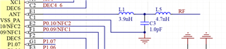
In the documentation, its suggested that the antenna should have a matching network between the WLCSP NRF52832 and the 50 ohm transmission line that looks like this:
Antenna manufacturers also recommend having a matching network in-between their antenna and the 50 ohm transmission line, often in the form of a pi network.
In many of the use cases for this product, the distance between the MCU and the antenna will be very small, often much smaller than 1/10th of the ~120cm wavelength of 2.4GHz. In this condition, it's likely that the transmission line is not very significant. In this case, is it possible to match the MCU antenna output directly to the antenna with a single Pi or T network, instead of having a T network and a Pi network?
