Hi,
I have develop an application using the nrf52832 combined wit the ICM20948 sensor.
The application use ESB communication between peripheral and central. I have solder 10 ohm resistor between the nrf52 board and the nominal 3V , and another one between the ICM20948 board and the 3 V supply.
When the ICM is not in used, I want to put the nrf52 in sleep mode for one second. The nrf52 then wake up and send the battery level to the central to keep communication going and also pickup new instruction from the returning acknowledge. This is the portion of the code use for the standby :
    else if (DMP_acq == 0)
           {  app_timer_start(m_timer, APP_TIMER_TICKS(1000), NULL);  //  timer one shoot  - events will wake up the sensor

            // Put the CPU to sleep until an interrupt is detected.   (data or timer)
            // Make sure any pending events are cleared
            __SEV();
            __WFE();
            // Enter System ON sleep mode
            __WFE();


            }
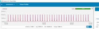
When in standby, I measure about 47 mV across the nrf52 10 ohm resistor. That would give about 4.7 mA. The ICM chip is almost at 0 mA. Number goes up approx to 7.5mA for the nrf52 board and 5 mA for the ICM board (12.5 mA) when sampling values at 56 Hz.
I suspect that I am doing something wrong. I would expect low uA value when the nrf52 is in standby, no sampling going on, using the above code .
I have seen a post with the following calculation:
System ON, no RAM retention + RTC + LFRC = 1.2uA + 0.1uA + 0.6uA = 1.9uA
I have RTC and LFRC, working for timestamp and +, nrf_clock for ESB
What am I doing wrong ?
(Note : Not sure what is no ram retention, should I clear the memory before going to sleep ?)
Thanks you in advance for your help. It's truly appreciated.