This post is older than 2 years and might not be relevant anymore
More Info: Consider searching for newer posts

Ceramic antenna and touch switch placement

Hello.

We are currently developing PCB design of smartwatch with RF Nordic nRF24 chip, Johanson small ceramic antenna (P/N 2450AT42B100), and capacitive Touch Switch (AT42Q1012). PCB size is very small: 17x38mm. In PCB one side is placed LCD and Touch Switch pin and on the other side all electronic components and Li-ion Polymer battery. I think that the antenna can affect the switch and inadvertently turn on/off the system.

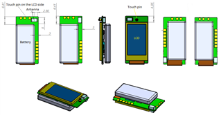
Here are various options for antenna placement on the PCB. I have no experience with RF.

The question is where to place the antenna so as not to get a random system on/off. 

Thanks.

Evgeni

Parents
  • Hi,


    You should replicate the mounting instructions for the antenna, described in the antenna datasheet, and the reference layout for the nRF24 which is described in the nRF24 Product Specification. If there is conflict with other components you should prioritize the antenna and nRF24 if you do not want RF performance to be degraded, especially if you do not have experience with RF. You should also consider submitting your design here for a review.


    Best regards,

    Andreas

Reply
  • Hi,


    You should replicate the mounting instructions for the antenna, described in the antenna datasheet, and the reference layout for the nRF24 which is described in the nRF24 Product Specification. If there is conflict with other components you should prioritize the antenna and nRF24 if you do not want RF performance to be degraded, especially if you do not have experience with RF. You should also consider submitting your design here for a review.


    Best regards,

    Andreas

Children
No Data
Related