
SDK: 15.3.0
BOARD: custom nRF52840 pre-product
Hi, I want to implement usb dfu trigger library.
but, faced with a problem.
My project are started from usb cli example.
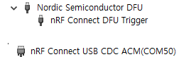
I have succeed to display DFU Trigger and CDC ACM in device manager.
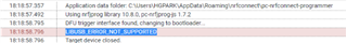
but, nrfutil and nrf-programmer failed to trigger dfu.
error: LIBUSB_ERROR_NOT_SUPPORTED
My sdk_config.h file, what I'm missing?
#ifndef APP_USBD_VID
#define APP_USBD_VID 0x1915
#endif

#ifndef APP_USBD_PID
#define APP_USBD_PID 0xC00A
#endif

#ifndef APP_USBD_NRF_DFU_TRIGGER_ENABLED
#define APP_USBD_NRF_DFU_TRIGGER_ENABLED 1
#endif

#ifndef NRF_DFU_TRIGGER_USB_USB_SHARED
#define NRF_DFU_TRIGGER_USB_USB_SHARED 1
#endif

#ifndef NRF_DFU_TRIGGER_USB_INTERFACE_NUM
#define NRF_DFU_TRIGGER_USB_INTERFACE_NUM 0
#endif

#ifndef NRF_CLI_CDC_ACM_COMM_INTERFACE
#define NRF_CLI_CDC_ACM_COMM_INTERFACE 1
#endif

#ifndef NRF_CLI_CDC_ACM_DATA_INTERFACE
#define NRF_CLI_CDC_ACM_DATA_INTERFACE 2
#endif

#ifndef APP_USBD_CONFIG_SELF_POWERED
#define APP_USBD_CONFIG_SELF_POWERED 0
#endif

#ifndef APP_USBD_CONFIG_MAX_POWER
#define APP_USBD_CONFIG_MAX_POWER 100
#endif

#ifndef APP_USBD_CONFIG_POWER_EVENTS_PROCESS
#define APP_USBD_CONFIG_POWER_EVENTS_PROCESS 1
#endif

#ifndef APP_USBD_CONFIG_EVENT_QUEUE_ENABLE
#define APP_USBD_CONFIG_EVENT_QUEUE_ENABLE 0
#endif
and add functions in main.c
void enable_reset()
{
    if (((NRF_UICR->PSELRESET[0] & UICR_PSELRESET_CONNECT_Msk) != (UICR_PSELRESET_CONNECT_Connected << UICR_PSELRESET_CONNECT_Pos)) ||
        ((NRF_UICR->PSELRESET[1] & UICR_PSELRESET_CONNECT_Msk) != (UICR_PSELRESET_CONNECT_Connected << UICR_PSELRESET_CONNECT_Pos)))
    {
        NRF_NVMC->CONFIG = NVMC_CONFIG_WEN_Wen << NVMC_CONFIG_WEN_Pos;
        while (NRF_NVMC->READY == NVMC_READY_READY_Busy){}
        NRF_UICR->PSELRESET[0] = 18;
        while (NRF_NVMC->READY == NVMC_READY_READY_Busy){}
        NRF_UICR->PSELRESET[1] = 18;
        while (NRF_NVMC->READY == NVMC_READY_READY_Busy){}
        NRF_NVMC->CONFIG = NVMC_CONFIG_WEN_Ren << NVMC_CONFIG_WEN_Pos;
        while (NRF_NVMC->READY == NVMC_READY_READY_Busy){}
        NVIC_SystemReset();
    }
}

/**
 * Function for configuring UICR_REGOUT0 register
 * to set GPIO output voltage to 3.0V.
 */
static void gpio_output_voltage_setup(void)
{
    // Configure UICR_REGOUT0 register only if it is set to default value.
    if ((NRF_UICR->REGOUT0 & UICR_REGOUT0_VOUT_Msk) ==
        (UICR_REGOUT0_VOUT_DEFAULT << UICR_REGOUT0_VOUT_Pos))
    {
        NRF_NVMC->CONFIG = NVMC_CONFIG_WEN_Wen;
        while (NRF_NVMC->READY == NVMC_READY_READY_Busy){}

        NRF_UICR->REGOUT0 = (NRF_UICR->REGOUT0 & ~((uint32_t)UICR_REGOUT0_VOUT_Msk)) |
                            (UICR_REGOUT0_VOUT_3V0 << UICR_REGOUT0_VOUT_Pos);

        NRF_NVMC->CONFIG = NVMC_CONFIG_WEN_Ren;
        while (NRF_NVMC->READY == NVMC_READY_READY_Busy){}

        // System reset is needed to update UICR registers.
        NVIC_SystemReset();
    }
}
if (NRF_POWER->MAINREGSTATUS &
    (POWER_MAINREGSTATUS_MAINREGSTATUS_High << POWER_MAINREGSTATUS_MAINREGSTATUS_Pos))
{
    gpio_output_voltage_setup();
}
enable_reset();
I don't fully understand this code. I got this from github in similar issue. link.
I also connected a gpio pin to reset pin.
