This post is older than 2 years and might not be relevant anymore
More Info: Consider searching for newer posts

Max30102 Heart rate module connected to nrf52 DK

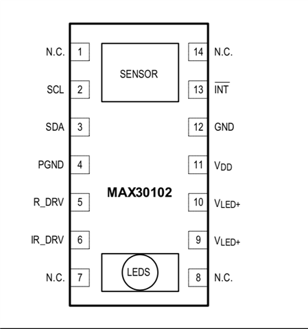
I am currently working on a Heart rate sensor(max30102). I have connected the sensor to my nrf52 DK as follows:

GND -> GND
VDD -> VIN
SCL -> P0.27
SDA -> P0.26
INT -> P0.17

I am working on the twi_sensor example from the sdk. I have used NRF_LOG_INFO(); and the example is running on the board but the sensor does not get initialized when called. i called a function that return the sensor i.d but the result ended with 0x00, in addition the LED's of the sensor are off.

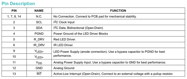
I am not sure what i am missing? I have not coded or configured anything regarding the INT pin.... I just plugged the pin into P0.17. The documentation as seen below says i should attach the INT pin to an external voltage with a pull-up resistor. How do i go about this on my nrf52 DK?

Other than the INT pin i do not see why the sensor wont initialize. Any help would be appreciated. Thank you.
Parents
  • Hello,

    First, could you specify which pin you are using as you "VIN" pin? From the looks of it, I will assume that the left side of your connections columns is the sensor, and the right side is the nRF52 DK. Is your sensor mounted on the nRF52 DK as an arduino shield?

    i called a function that return the sensor i.d but the result ended with 0x00, in addition the LED's of the sensor are off.

    Does the sensor react at all to being powered up? Does it indicate in any way that it is powered on and functioning?
    If you are in doubt whether your code could be at fault in detecting and returning the device ID, then you may want to try out the TWI_Scanner example from the SDK - to verify if the sensor is responding at all.

    The documentation as seen below says i should attach the INT pin to an external voltage with a pull-up resistor. How do i go about this on my nrf52 DK?

    I am not sure I understand the direction of the interrupt - who is controlling this pin?
    To see a demonstration of how GPIO configuration can be done, you could check out the Pin Change Interrupt example.
    The input pin in the example is configured with pullup, and if it is the other way around you can just set it as an output that defaults to high.

    For safe measure I will also include the link to the Pin Assignment  for the nRF52832.

    Best regards,
    Karl

Reply
  • Hello,

    First, could you specify which pin you are using as you "VIN" pin? From the looks of it, I will assume that the left side of your connections columns is the sensor, and the right side is the nRF52 DK. Is your sensor mounted on the nRF52 DK as an arduino shield?

    i called a function that return the sensor i.d but the result ended with 0x00, in addition the LED's of the sensor are off.

    Does the sensor react at all to being powered up? Does it indicate in any way that it is powered on and functioning?
    If you are in doubt whether your code could be at fault in detecting and returning the device ID, then you may want to try out the TWI_Scanner example from the SDK - to verify if the sensor is responding at all.

    The documentation as seen below says i should attach the INT pin to an external voltage with a pull-up resistor. How do i go about this on my nrf52 DK?

    I am not sure I understand the direction of the interrupt - who is controlling this pin?
    To see a demonstration of how GPIO configuration can be done, you could check out the Pin Change Interrupt example.
    The input pin in the example is configured with pullup, and if it is the other way around you can just set it as an output that defaults to high.

    For safe measure I will also include the link to the Pin Assignment  for the nRF52832.

    Best regards,
    Karl

Children
No Data
Related