This post is older than 2 years and might not be relevant anymore
More Info: Consider searching for newer posts

Max30102 Heart rate module connected to nrf52 DK

I am currently working on a Heart rate sensor(max30102). I have connected the sensor to my nrf52 DK as follows:

GND -> GND
VDD -> VIN
SCL -> P0.27
SDA -> P0.26
INT -> P0.17

I am working on the twi_sensor example from the sdk. I have used NRF_LOG_INFO(); and the example is running on the board but the sensor does not get initialized when called. i called a function that return the sensor i.d but the result ended with 0x00, in addition the LED's of the sensor are off.

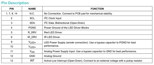
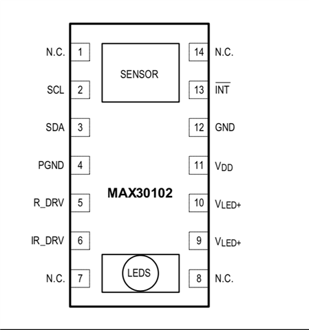
I am not sure what i am missing? I have not coded or configured anything regarding the INT pin.... I just plugged the pin into P0.17. The documentation as seen below says i should attach the INT pin to an external voltage with a pull-up resistor. How do i go about this on my nrf52 DK?

Other than the INT pin i do not see why the sensor wont initialize. Any help would be appreciated. Thank you.

Parents
  • Thanks for the reply Karl.

    1.) I connected the VIN pin of my sensor to my VDD of the nrf52 DK. Secondly, i do not have an arduino shield....the sensor connections go straight to the nrf DK.

    2.) Im supposed to see a red LED light up when the sensor is powered up but i do not see anything. I have used the initialization code of the sensor on my custom PCB board and the sensor starts up. I also used the twi_scanner as suggested and got this:


    Why are there twi devices detected at 9 different addresses?

    3.) I have not tried configure the gpio pin for the INT but to answer your question on who is controlling the pin?.....im not sure i understand the question well but i am really not sure what to do with the INT pin and i have a feeling it is the reason my sensor is being weird on the nrf52DK. 

Reply
  • Thanks for the reply Karl.

    1.) I connected the VIN pin of my sensor to my VDD of the nrf52 DK. Secondly, i do not have an arduino shield....the sensor connections go straight to the nrf DK.

    2.) Im supposed to see a red LED light up when the sensor is powered up but i do not see anything. I have used the initialization code of the sensor on my custom PCB board and the sensor starts up. I also used the twi_scanner as suggested and got this:


    Why are there twi devices detected at 9 different addresses?

    3.) I have not tried configure the gpio pin for the INT but to answer your question on who is controlling the pin?.....im not sure i understand the question well but i am really not sure what to do with the INT pin and i have a feeling it is the reason my sensor is being weird on the nrf52DK. 

Children
  • Hello,

    LASHCA@PIETERSE said:
    Thanks for the reply Karl.

    No problem at all, I am happy to help!

    LASHCA@PIETERSE said:
    1.) I connected the VIN pin of my sensor to my VDD of the nrf52 DK. Secondly, i do not have an arduino shield....the sensor connections go straight to the nrf DK.

    This does not match the rest of your description in the " -> " connection description and the pin names in the MAX figure you included, which is confusing. For future reference, a rough connection diagram is highly appreciated to better understand what connections you have made.
    Since you mention that you connect the VIN pin on the sensor to the VDD pin on the nRF52 DK, and there is no VIN pin on the MAX figure, but there does exist a pin referred to as VIN on the DK - could you confirm which pin on the DK you connected the VDD pin of the MAX to?
    I do not intend to come off as crass - I just want to make sure I have understood your setup correctly.

    LASHCA@PIETERSE said:
    2.) Im supposed to see a red LED light up when the sensor is powered up but i do not see anything. I have used the initialization code of the sensor on my custom PCB board and the sensor starts up. I also used the twi_scanner as suggested and got this:

    Do you have the datasheet or user manual for the sensor?
    If you are supposed to see the LED light up when the sensor is powered, then my guess would be that the sensor is not powered(or currently functioning). If I suspect this is the case, I double check all its connections.

    LASHCA@PIETERSE said:
    Why are there twi devices detected at 9 different addresses?

    What addresses does your sensor breakout board have? It could have multiple addresses.
    Though something might be off here, since all the addresses are from 1 through 9.

    LASHCA@PIETERSE said:
    3.) I have not tried configure the gpio pin for the INT but to answer your question on who is controlling the pin?.....im not sure i understand the question well but i am really not sure what to do with the INT pin and i have a feeling it is the reason my sensor is being weird on the nrf52DK. 

    That might explain things, yes. Do you have the sensors datasheet?
    It is probably that the INT pin dictates the sensors behavior. I would read about what is expected and how to control the sensor in the datasheet or userguide. It is also important to know if the pin is meant to generate an interrupt on the DK side, or if it is meant as a way for the DK to generate an interrupt on the sensor side.
    This will be crucial to know when you configure your GPIO - and when that time comes, I highly recommend taking a look at the pin change interrupt example I referenced in my last post.

    Please do not hesitate to ask if you should have any questions or if things still are unclear!

    Best regards,
    Karl

Related