This post is older than 2 years and might not be relevant anymore
More Info: Consider searching for newer posts

Using nRF5340-PDK at 3.3V instead of 1.8V

I want to interface the nRF5340-PDK board to a different vendor's board that runs at 3.3V.

I'm using the SPI bus to communicate between the two boards

Using the nRF5340-PDK board in its default state as it comes from the factory, the SPI bus signals are 1.8V

What changes do I need to make to the switch settings, power connections, modifications, etc to make the nRF5340-PDK produce SPI signals at 3.3V?

What software changes are needed?

I've already tried figuring it out on my own.

I've already tried changing some UICR registers using nrfjprog, and I've already tried doing several things with switch positions and power connections, but the board appears to have lots of options for configuring the power and I may have missed something.  

Parents
  • Hi,

    It should be sufficient to write the VREGHOUT UICR register:

    nrfjprog --family nrf53 --memwr 0x00FF8010 --val 5

    I tested this on the DK, and it sets the GPIO output to 3.3V when running from 5V power source.

    Note that if you have previously written 0 to this register, you need to do an eraseall operation before you can write it again:

    nrfjprog --family nrf53 --memwr 0x00FF8010 --val 5
    Parsing parameters.
    Writing.
    
    nrfjprog --family nrf53 --memrd 0x00FF8010
    0x00FF8010: 00000005                              |....|
    
    nrfjprog --family nrf53 --memwr 0x00FF8010 --val 7
    Parsing parameters.
    ERROR: The area to write is not erased.
    
    nrfjprog --family nrf53 -e
    Erasing user available code and UICR flash areas.
    Applying system reset.
    
    nrfjprog --family nrf53 --memwr 0x00FF8010 --val 5
    Parsing parameters.
    Writing.

    Best regards,
    Jørgen

  • Are you able to get 1.8 V GPIO output when running from J2 USB connector? I believe this will always go through the onboard 3 V buck regulator and power the nRF5340 through the VDD pin in Normal voltage mode. As described in GPIO levels, the GPIO voltage can only be configured when running in high-voltage mode:

    "In normal voltage mode, the GPIO high level equals the voltage supplied to the VDD pin. In high voltage mode, it equals the level specified in the VREGHVOUT register."

Reply Children
  • Well, I could have sworn that I was measuring 1.8V before I tried making changes, but when I erase UICR and put SW9 back to "VDD" and remove the power at P27, then I'm measuring VDD at 3.0V and VDDnRF_HV at 3.0V.

    I confirmed with an nRF5340-PDK new out of the box.

    So it sounds like rather than adjusting UICR registers I want to change the 3.0V regulator to 3.3V.

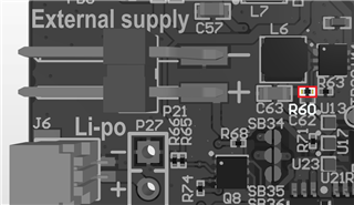
    U11 is the regulator and if I change R60 from 330k to 375k then that should give 3.3V

    I didn't have a 375k resistor in an 0201 package, but was able to make a 374k in 0402 package work

    Now VDD measures 3.3V

    So I guess this is the way to do it if you don't want to use a separate supply (no UICR changes needed, but you need to modify the board)

    Let me know if there's a better way to do this for using J2 power only.

Related