
Hello,
in keeping with the low power theme,
I'm looking for some help in understanding the relationship between the pcb thickness, antenna trace and range.
Using the reference design for the nRF52832, FR4 2-layer pcb at 1.6 mm thick, antenna length at 25 mm (width 1.5 mm), achieving 2.44 GHz, range 20 meters at 0 dBm Tx output power, (except for pcb thickness, other values are just for illustration).
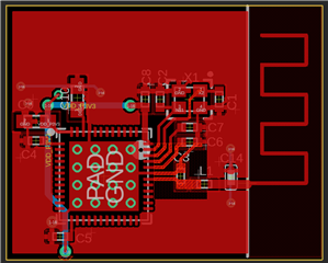
To achieve the same 20 meter range as the 1.6 mm pcb, if the pcb is now 0.8 mm thick, is it just a matter of trimming the antenna length down to say 23 mm, and adjusting the pi network accordingly?
And if pcb thickness is reduced even more to 0.6 mm, then only more trimming and pi tuning is needed to keep Tx at a steady 0 dBm to achieve 20 meters?
Basically the question is, if I keep making the pcb thinner (up to a point), I can still get 20 meters at 0 dBm by only having to trim the antenna and tune the pi or is there more to consider?
Or the trimming and pi tuning only go so far that after 0.6 mm thickness the range will be less than 20 meters at 0 dBm ?
Also,
(I'll add this here rather than a new question),
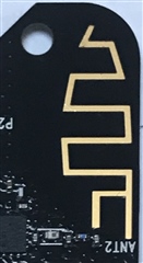
other than gold being non-corrosive, what performance benefit (if any), is having an ENIG finish on the antenna trace?
ENIG
Solder Masked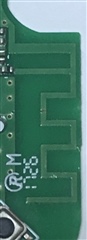
thank-you,

