
I have already set up a successful sender and receiver. The receiver was using an arduino board and the sender a avr at90usb162. I have now removed the arduino and moving closer to pre-production but getting a bit of a snag.
The two device must be able to detect one another. The current code I have does the following.
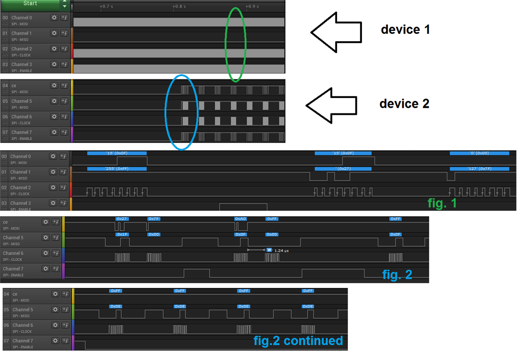
Device 1) Loop a status register check followed by an immediate clear int's (0x27, 0x7f). The idea is if the status register ever sees a 0x40 or maybe 0x20 we know it saw data.
I was hoping an 0x20 would work but it didnt, so I added a ox40 but they never are set.
while (1)
{
    if ( READ_MODE != _NRF24_IN_ )
	{
		if  (wirelessInterface->dataReady())
		{
			WRITE_MODE = _NRF24_;
			return;
		}
  	}
}
dataReady
SPCR |= (1<<SPE);//turn on spi.

	enable();
	unsigned char status=sendCommand(0xFF); //nop
	disable();

	clearALLFIFO(); //4f - because once we confirm a read, we need to allow it to read later.
	                //1f - because too many reads cause a time out and this should be endless.
	SPCR &= ~(1<<SPE);//power down SPI
	if (status & 0x40) return 1;
	if (status & 0x20) return 1;
	return 0;
}
device 2) loops a send data and wait for ack. This should make device 1 aware of its presence buy it it not working.
while (1)
{
    if (WRITE_MODE != _NRF24_)
	{
		if ( wirelessInterface->get(0xFF) == 0x0a)
		{
			READ_MODE = _NRF24_IN_;
			return;
		}
	}
}
the idea here is that it will get an 0x0a from the device 1 if it wakes up and replies but it never does...
the get function starts like so. This sends a 0xff for its data.
	enable();				   //   |clears ints, f is ignored
	sendCommand(0x27);sendCommand(0x7F);
	disable();
	pulse();

	enable();
	sendCommand( 0xA0 );
	sendCommand(data);
	disable();
	pulse();
Here are some details, note fig.1 is always 0x0f. The idea is it should go to 0x2f when the data arrives.
NOTE2:
both modules are with in 4 inches because I need to use the same analyzer. If that is an issue, what can I put between them (foil?) ?
Both chips are the same hex, the only difference is the init code is set with a 1 or a 0 to select the operational mode.
//set up the NRF24
	enable();
	sendCommand(0x20);sendCommand(0x0A | master);//Config : 00001010 enalbe crc 1 byte, power up, ptx/rx
	disable();

	if (master ) clearReadFIFO();

	_delay_ms(2); //power up delay

	//set channel to 5.
	enable();
	sendCommand(0x25);sendCommand(2);
	disable();

	//18db and  rate of 2mb speed
	enable();
	sendCommand(0x26);sendCommand(0x0F);
	disable();

	//addres for 5 (0011) bytes
	enable();
	sendCommand(0x23);sendCommand(3);
	disable();

	//dynamic length for all pipes
	enable();
	sendCommand(0x3C);sendCommand(3);
	disable();

	//enable ack payload and dynamic
	enable();
	sendCommand(0x3D);sendCommand(7);
	disable();

	enable();
	sendCommand(0x22);sendCommand(0x3f);//enable all RX pipes
	disable();

	//must match to auto ack
	enable();//tx address
	sendCommand(0x30);sendCommand(0xe7);sendCommand(0xe7);sendCommand(0xe7);sendCommand(0xe7);sendCommand(0xe7);
	disable();

	enable();//rx address
	sendCommand(0x2A);sendCommand(0xe7);sendCommand(0xe7);sendCommand(0xe7);sendCommand(0xe7);sendCommand(0xe7);
	disable();
	clearReadFIFO();
	ATT_ON();_delay_us(10);ATT_OFF();//palse

