This post is older than 2 years and might not be relevant anymore
More Info: Consider searching for newer posts

MS88SF2 Power Configuration

Hello,

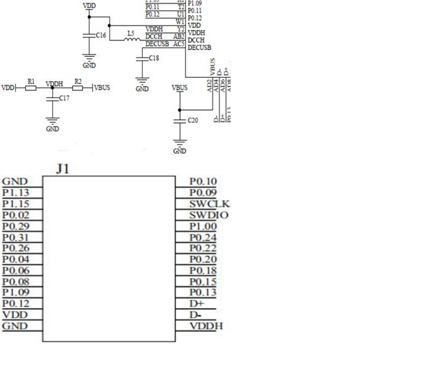
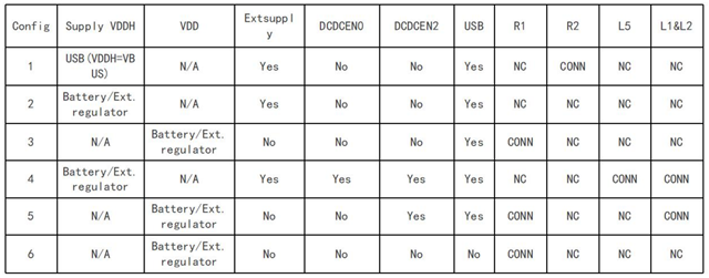
For our project we were planning on using a 3rd party module MS88SF2 (nRF52840), which schematic snapshot is provided and which will be powered though the  li-po battery. Full documentation is available here. What confused me was power configuration they selected to use which I couldn't identify from any of the given examples on the design references (starting page 688). If I understand it right, the way how the chip module operates is as follows:

If 3.3V is applied to VDD, then VDDH = VDD due to resistor R1 and the chip thus enters “Normal Voltage Mode”, where REG0 is not used. If 5V is applied to VDDH, the chip goes into “High Voltage Mode” and then DCDC converter is used to set VDD to be some lower voltage e.g. 3.3V. The implications though will be that current will flow from VDDH to VDD, which depends on the resistor R1. At the same time VBUS = VDDH due to connected resistor R2 and the USB module gets powered together with the chip, thus allowing to program the chip through the USB. The take away is that when powering from the battery, use a 3.3V regulator to provide correct voltage on VDD, however when on USB, use 5V on VDDH, which will consume slightly more power due to the current flowing through the resistor R1. Is that correct and do you think that the configuration they chose will not have any further implications to the way how the module operates? I also contacted the supplied as they did not provide R1 and R2 values..

I hope you will be able to help me even though this is a 3rd party module, thanks!

  • Was further checking the docs and noticed that the provided configuration table coincides with the design references to a degree, assuming that R1 and R2 are just short circuits. For example the Config 4 has REG0 and REG1 in DCDC enabled and 5 is on Normal Voltage Mode and REG1 is DCDC enabled. However I didn't notice them selling different configurations, thus maybe there is a way to select the desired configurations using some built-in electronically programmable switch...

  • Hi 

    I am pretty sure your original summary is correct. 

    If you are looking for optimal current consumption you should use VDD only, and use an external regulator to get the supply voltage within the legal range of VDD. 

    If you want to use the USB interface of the nRF52840 then you can use the VDDH line for 5V supply. In this case there might be some current leakage through R1, but the assumption is probably that you are not so worried about current consumption when you are supplying power from the USB interface. 

    If you have a decent ammeter available (or a power profiler) you could try to power the module through VDDH, and see how high the currents are in active and sleep modes. Compare that to the current draw when running through VDD, and you should get an impression of the difference between the two. 

    Are you thinking of connecting your LiPo battery directly to VDDH to avoid the need for an external regulator?

    Best regards
    Torbjørn

Related