This post is older than 2 years and might not be relevant anymore
More Info: Consider searching for newer posts

nRF52840 ANT matching circuit

Hi

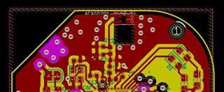
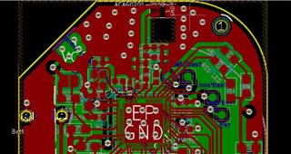
we are using the nRF52840 and antenna signal i connected ceramic chip antenna(ACAG020-2450-T).


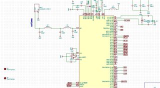
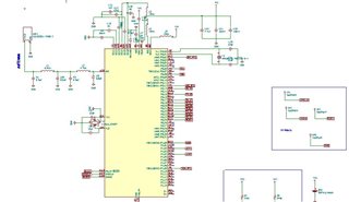
The above attached schematic of ant signal matching circuit schematic.

The below is the antenna datasheet link.

https://abracon.com/datasheets/ACAG0201-2450-T.pdf

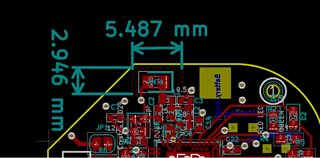
Kindly check the antenna area matching circuit.

Please suggest if any changes/modifications required ASAP.

Regards

Bala

Parents Reply
  • That won't work well. You need a ground plane on the top layer. Using tracks to connect ground is not going to work at these frequencies. Take a look at  the reference layout to see how it's done. 

    C3, C8 and L7 shall be placed like this: 

    Note how C3 here is grounded only to the VDD_PA pin and the center pad.

    It's _very_ important that you follow the antenna manufacturers reference layout: 

    (from the antenna datasheet)

    Every dimension must be correct!

Children
Related