This post is older than 2 years and might not be relevant anymore
More Info: Consider searching for newer posts

Vdd generated from Vddh is unstable without connected debuger and with non-started soft device

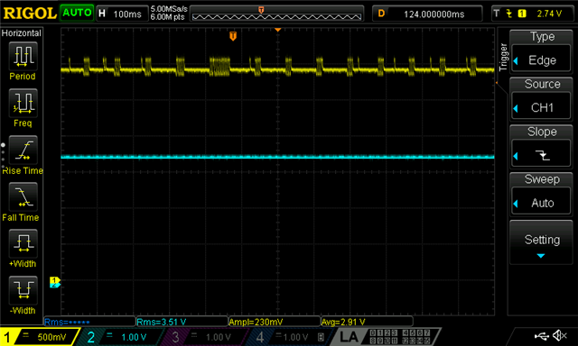
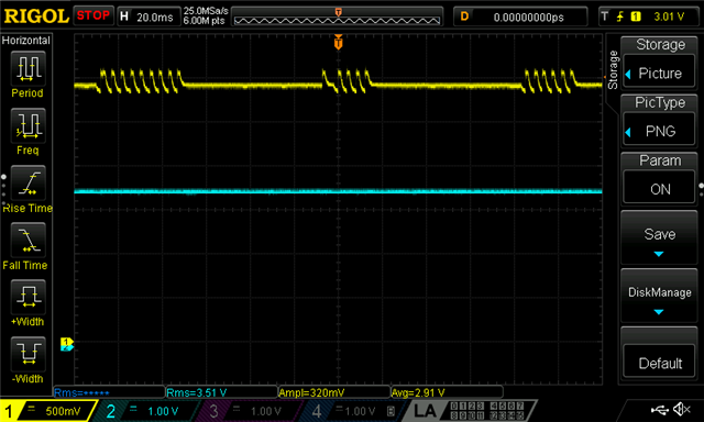
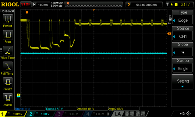
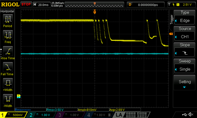
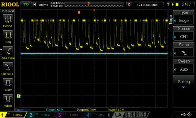
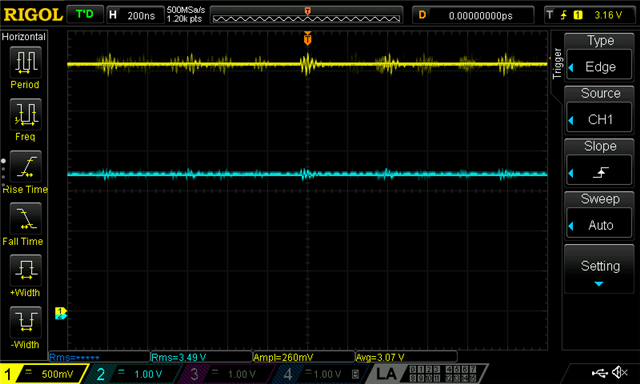
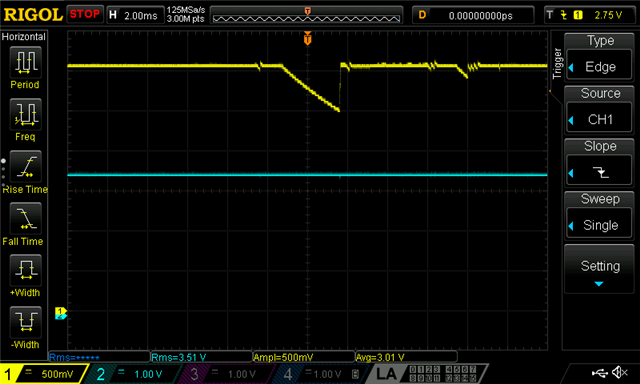
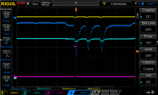
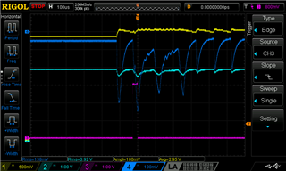
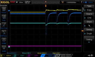
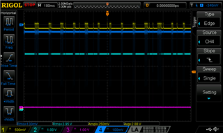
Vdd generated from Vddh is unstable without connected debugger and with non-started soft device

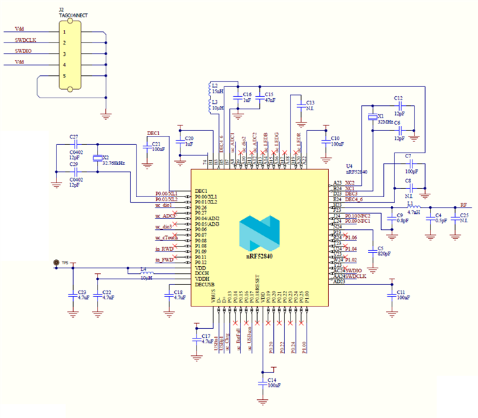
We are developing a battery powered device based on nRF52840 on custom PCB. We are aiming to use nRF52840 DCDC REG0 to provide 3V Vdd from Li-ion battery. Vdd would also be used to run some peripherals but the current should be below 25 mA. Firmware was developed on nRF52 DK and successfully ported to custom board. With exception of unstable Vdd.

The circuit is made based on the circuit configuration no. 4 from nRF52840 datasheet v 1.1 p591. Inductors L2, L3 and capacitors C15 and C16 are in place. Also all other capacitors and inductors). Vdd is stable when the debugger (nRF52 DK) is connected. REG0 DCDC converter (and REG1 also) is enabled between initialize() and start() function in main (based on mesh light server example).

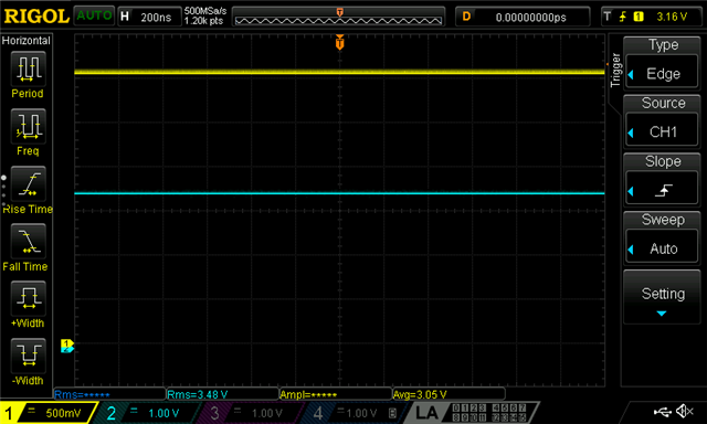
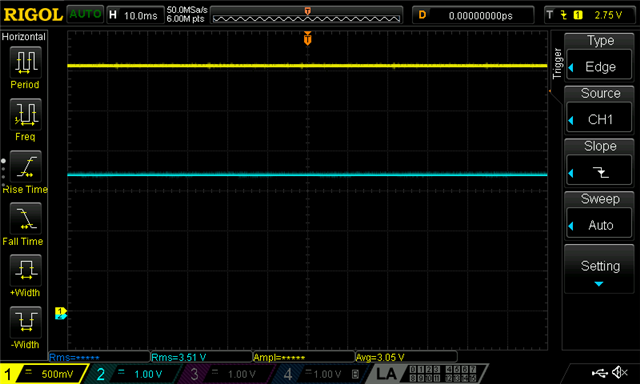
As long as I program the CPU with the debugger and then reset it via SWDebug the Vdd is stable. Even if I disconnect the debugger, the circuit stays stable. As soon as I start the circuit by connecting it to external supply (the same as used previously for programming) Vdd becomes unstable.

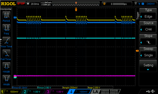
For debugging purposes I did not start the soft device while experimenting. After two days of debugging several sub circuits and playing with blocking capacitors, I checked the code again and out of desperation (and function name: sd_power_dcdc0_mode_set(NRF_POWER_DCDC_ENABLE);) enabled the soft device (just before writing to forum) and the Vdd stayed stable even if the circuit was started by connecting external supply only without debugger.

This seems like a very odd bug (or I missed some warnings somewhere).

My question now is, whether this behavior is expected? It seems very strange.

Thank you!

Parents
  • Hi, sorry for the late response. Some voltage changes are expected when the regulator is switching between the different modes. ULP and DCDC/LDO. But based on your description I'm not sure about what you are seeing, vs what is expected. Do you have any plots you can share? Also if you can share the schematics that would be great. We can make this ticket private if you don't want to share it publicly.

  • Dear Stian,

    It is ok, my reply is also very late due to some holidays and other matters.

    I have done some more tests and scope screenshots. First, here is the main part of schematics without peripheral circuits:

    Schematics

    Circumstances during the experiment.

    The PCB was battery powered (Li-ion 3.5V), DCDC0 and DCDC1 were enabled, Vdd was programmed to 3V. We are using nRF52840, nrf5 SDK for mesh v4.0 and nrf SDK 16.0. Firmware is based on the Light Switch Server example. Core source files regarding Bluetooth were not modified. For programming our PCB we use nrf52DK via SWD (using P20 (GND detect, SWD CLK, SWD IO, VTG and _no_ VDD) and GND connected to GND detect). CH1 is Vdd, CH2 is Vbat. Initially the soft device was not enabled and the debugger was not connected.

    Here are oscilloscope screenshots and some explanations:

    Vdd with no SD:

    Then drops in Vdd happen for no obvious reason:

    Then I connect the debugger via SWD:

    And reset the microcontroler via Segger Embedded Studio:

    Then I stopped the execution via Segger:

    Now I reprogrammed the firmware and enabled the soft device. Here we have our Vdd when the uc operates reliably despite some small oscillations:

    After disconnecting the DK the Vdd is constant:

    After resetting the PCB by reconnecting the battery the Vdd is still constant:

    But there are ocasional drops in Vdd:

    I hope that based on this information you will be able to identify the problem or at least give some ideas about what could be causing Vdd instability. Currently the main problem is that because of Vdd instability, the touch button reports false signals. But finally we have to solve this issue, because it may lead to other problems.

    Thank you,
    Matevz

Reply
  • Dear Stian,

    It is ok, my reply is also very late due to some holidays and other matters.

    I have done some more tests and scope screenshots. First, here is the main part of schematics without peripheral circuits:

    Schematics

    Circumstances during the experiment.

    The PCB was battery powered (Li-ion 3.5V), DCDC0 and DCDC1 were enabled, Vdd was programmed to 3V. We are using nRF52840, nrf5 SDK for mesh v4.0 and nrf SDK 16.0. Firmware is based on the Light Switch Server example. Core source files regarding Bluetooth were not modified. For programming our PCB we use nrf52DK via SWD (using P20 (GND detect, SWD CLK, SWD IO, VTG and _no_ VDD) and GND connected to GND detect). CH1 is Vdd, CH2 is Vbat. Initially the soft device was not enabled and the debugger was not connected.

    Here are oscilloscope screenshots and some explanations:

    Vdd with no SD:

    Then drops in Vdd happen for no obvious reason:

    Then I connect the debugger via SWD:

    And reset the microcontroler via Segger Embedded Studio:

    Then I stopped the execution via Segger:

    Now I reprogrammed the firmware and enabled the soft device. Here we have our Vdd when the uc operates reliably despite some small oscillations:

    After disconnecting the DK the Vdd is constant:

    After resetting the PCB by reconnecting the battery the Vdd is still constant:

    But there are ocasional drops in Vdd:

    I hope that based on this information you will be able to identify the problem or at least give some ideas about what could be causing Vdd instability. Currently the main problem is that because of Vdd instability, the touch button reports false signals. But finally we have to solve this issue, because it may lead to other problems.

    Thank you,
    Matevz

Children
  • I would like to add a few more things that I have tried.

    1. If I disable DCDC REG0, Vdd is stable, regardless whether soft device is enabled or not.
    2. There are some IR LEDs that are powered from Vdd and should draw about 50 mA for several us, but when they are switched on, the Vdd does not drop or oscillate.
    3. There are some other peripherals, but they should not do anything during testing, with exception of capacitive touch button controller, but that one should be limited to 400 uA.
  • Hi, 

    Stian is out of office on vacation, I will have a look at this within the end of the week. 

    Best regards,
    Kaja

  • Could you do some measurements of current drawn from the battery, when this happens? 

    Have you measured the peak current draw from the external devices that are powered from VDD? 
    - Could you verify that non of them is higher then 25 mA? 


    Best regards,
    Kaja

  • Hi Kaja,

    Thanks for reply. I have done additional measurements of current draw from the battery and unfortunatelly I can not verify that none of the currents is higher than 25 mA. I am aware of this limitation from the datasheet and  we did not expect to reach it (At this stage an LED is still on for 25us instead of 5us. However, I don't think this is the sole reason for instability. Please bear with me for the explanation.

    There will be 4 channels from the scope.
    - CH1: Vdd
    - CH2: Vbat (charged to about 4 V)
    - CH3: LED trigger (active high)
    - CH4: Voltage on 10 ohm resistor between GND and battery minus. Scope is grounded to GND, and with resolution of 100 mV/div, it gives current measurement with -10 mA/div.
    For all cases, soft device was not enabled, debugger was connected but powered down (it behaves the same as if it was disonnected).

    Fig 1. ) Reg0: LDO, trig: CH4: Ibat > 35mA

    Too high current drain can be seen here or 25 us, where Ibat reaches almost 40 mA (most of this should be through Vdd). The reason for this is the LED - CH3 is the control signal for it. The same is repeated twice more after about 100 us.

    Fig 2.) Reg0: DCDC, trig CH3: LED control signal

    Similar pattern can be seen when DCDC is used for Reg0. But here, there is another spike before the LED causes high current drain, and after the other two LEDs' cycles the "oscillations" continue.

    Fig 3.) Reg0: DCDC, trig: CH4: Ibat > 35mA

    Here I changed the trigger to CH4 (Ibat) and here high current drain from battery occurs even when the LED does not turn on. I could not get the same circumstances (i.e. high current drain without LED on) when using LDO.

    Fig 4.) Same as 3, but different time scale to show the periodicity (or the lack of it) if it indicates something...

    When I measured 1, I was sure that too high current drain was the reason, but then the spike before the LED is turned on in Fig 2 looked suspicious. And occurrence of high current drain from the battery without the LED only when DCDC is used for Reg0 confirms that there must be something else. There is the exact same firmware used for all cases (except enabling DCDC for Reg0), and no high current drain from the battery occurs when LDO is used (except when the LED is on)

    We will need to reduce the current drain by the LED, but I am afraid that this won't solve the whole issue, therefore I am still asking for advice.

    Thank you!

  • Hi,

    sorry for the delayed answer! 

    This really is not my strongest topic, Stian is back at the office on Monday! I hope he can give some good advice next week! 

    Best regards,
    Kaja

Related