This post is older than 2 years and might not be relevant anymore
More Info: Consider searching for newer posts

nRF52 antenna design without J1 coaxial connector

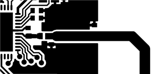
We're just finishing our layout for a custom nRF52832 board. According to the "General PCB design guidlines for nRF52 series" we copied the complete nRF layout from your reference design. But the reference design also includes the J1 coaxial connector which is not needed in our product.

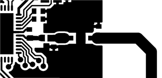
So now my question is how to exclude J1 without decreasing the performance or changing the impedance. My first approach would be to delete J1 and extend the transmission line to L1. Can this be done without changing the performance or is there another/better way?

Kind regards

Parents
  • Hi,

    as far as I can tell the purpose of the connector is to simplify the RF tuning procedure. The procedure will help you to reach maximum antenna efficiency and range and is highly recommended before going to production. The connector itself doesn't affect RF performance. On the other hand, removing the connector will reduce the BOM cost and save some PCB space.

    For my own designs I don't use the connector because of space constraints, but will happy to keep it if I could. This might be especially handy if the board is planned to be reused in various designs where it may be required to adjust the matching network. Removing the connectro as you've shown above will likely detune the antenna, but not dramatically either - it should work anyway, only closer until tuned.

    Please also take a look to the antenna tuning whitepaper: https://infocenter.nordicsemi.com/pdf/nwp_017.pdf

    Best regards,
    Mishka

  • Hi,


    Thanks for your answer, Mishka. Just to add on this, it is perfectly possible to tune the RF circuitry without a similar connector. You would then cut the transmission line and solder a coaxial cable with the outer conductor to the ground pour and the center conductor on the transmission line leading to either the radio or the antenna (depending on what part of the design you plan on tuning). This J1 SMD connector only leads to the radio, so you would need to do something similar, or resolder and rotate J1 in order to tune the antenna.

    Another common use case for this component is production testing, if you want to do detailed characterization of the RF performance.


    Also it is probably true that removing this could detune the antenna slightly, especially if the antenna narrow-banded and the connector is quite close to the antenna. The antenna should always be tuned in the final PCB and assembly though, so you would fix the detuning through this.


    Best regards,

    Andreas

Reply
  • Hi,


    Thanks for your answer, Mishka. Just to add on this, it is perfectly possible to tune the RF circuitry without a similar connector. You would then cut the transmission line and solder a coaxial cable with the outer conductor to the ground pour and the center conductor on the transmission line leading to either the radio or the antenna (depending on what part of the design you plan on tuning). This J1 SMD connector only leads to the radio, so you would need to do something similar, or resolder and rotate J1 in order to tune the antenna.

    Another common use case for this component is production testing, if you want to do detailed characterization of the RF performance.


    Also it is probably true that removing this could detune the antenna slightly, especially if the antenna narrow-banded and the connector is quite close to the antenna. The antenna should always be tuned in the final PCB and assembly though, so you would fix the detuning through this.


    Best regards,

    Andreas

Children
Related