Hello All,
I was interested in exploring the nRF52833 and didn't want to spend the money on a nRF52833 DK. Well I guess most of you can guess how that goes.
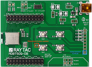
I purchased two pieces of the MDBT50Q-DB-33 which are only $20 from Amazon which has the nRF52833 on it as a module.
Looking at the schematic of the MDBT50Q-DB-33 compared to that of the nRF52833-DK it looks very similar from a pushbutton and LED perspective. Of course there is no J Link but I have a couple debuggers.
I am interested to know the RF range of the product so I looked at using the example as noted in this thread, https://devzone.nordicsemi.com/nordic/nordic-blog/b/blog/posts/testing-long-range-coded-phy-with-nordic-solution-it-simply-works-922075585?CommentId=777e02a3-9a4f-4ddf-a226-51edd9165980
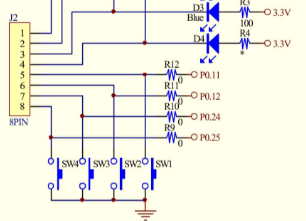
The example uses SW3 and SW4. Pressing SW3 on the MDBT50Q-DB-33 does work to make the device go into tho the tester mode. Unfortunately, pressing SW4 does not make the device work by using the BOARD_DUMMY_BUTTON when defined as BSP_BUTTON_3.
According to the schematic provided by Raytac, SW4 should be connected to P0.25, which is the same as the nRF52833 DK.
Here is a link to the nRF52833 DK Buttons and LED section.
https://infocenter.nordicsemi.com/index.jsp?topic=%2Fstruct_nrf52%2Fstruct%2Fnrf52833.html&cp=3_1
Just using the hex from the ble_app_att_mtu_throughput example didn't work.
To investigate if the switch was changing state when pressed, I hooked up a Logic Saleae Analyzer to the pin labeled as P0.25 (which should have been J3, pin 13) and pressed the button. I could not see the state of pin change. I checked all of the other switches and could see that they were high until I pressed on the switch, at which point the line would go low. I then checked with a meter and found that SW4 appears to be connected to pin 14 of J4 which is marked as a NC (this should have been connected to P0.25).
In main.c (of the ble_app_att_mtu_throughput example) here is the definition for the buttons for the example..
#define BOARD_TESTER_BUTTON BSP_BUTTON_2 /**< Button to press at the beginning of the test to indicate that this board is connected to the PC and takes input from it via the UART. */
#define BOARD_DUMMY_BUTTON BSP_BUTTON_3 /**< Button to press at the beginning of the test to indicate that this board is standalone (automatic behavior). */
I changed the BOARD_DUMMY_BUTTON to BSP_BUTTON_1 and reloaded the firmware onto one of the boards. I was then able to press SW2 and get the example to run.
I have reached out to Raytac and asked them to review this.
I am hoping this would help anyone that might be experimenting with the MDBT50Q-DB-33.