This post is older than 2 years and might not be relevant anymore
More Info: Consider searching for newer posts

nRF52832 - Initial values for capacitors for NFC coil

Hi all.

I did a layout with NFC antenna with a nRF52832 chip.

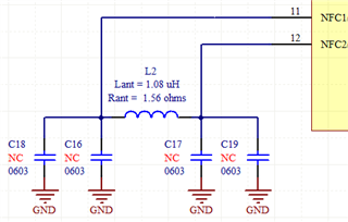
In the schematic (suggesten on datasheet) I have antenna coil with 2 capacitors to ground.

Drawing of NFC coil on layout:

There is two round holes at the start and end of the coil, the total lenght of coil is 455mm. It follows this design of ST's online tool eDesignSuite.

It is to have 1.08uH and 1.56 ohms.

Resistance was calculated with an  online tool.

Considering these informations, what values of capacitors (C16 and C17) I could use as a starting point for my PCB prototype?

Regards,

Jeferson.

Parents Reply
  • Hi Kaja.
    I really apreciate your help.

    There is no ground arm nor other signals on the antenna area.

    I did added more two capacitors, one on each NFC pin, on each end of the antenna.

    The estimated inductance is 1.08uH, so here goes my calculation.

    This part of equation:

    ((2*pi*13.56*1000000)^2) * 1.08*10^-6
    Result = 7.839*10^9

    Now doing substituition on the complete equation:

    Ctune = (2/(7.839*10^9)) - 0 - 4*10^-12
    Ctune = 2.511*10^-10
    Ctune = 251pF
    Ctune = 220pF + 30pF (commercial values)

    Does this seem correct for you?

    Regards,
    Jeferson.

Children
Related